(No.YF124)1-17
•
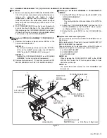
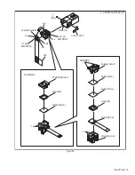
Chip IC replacement jig
To be used for adjustment of the camera system.
•
Cleaning cloth
Recommended the Cleaning cloth to wipe down the video
heads, mechanism (tape transport system), optical lens sur-
face.
•
Guide driver
To be used to turn the guide roller to adjustment of the linarity
of playback envelope.
•
INF adjustment lens
To be used for adjustment of the camera system. For the
usage of the INF adjustment lens, refer to the Service Bulletin
No. YA-SB-10035.
•
INF adjustment lens holder
To be used together with the Camera stand for operating the
Videocamera in the stripped-down condition such as the sta-
tus without the exterior parts or for using commodities that are
not yet conformable to the interchangeable ring. For the usage
of the INF lens holder, refer to the Service Bulletin No. YA-SB-
10035.
•
Mini stand
To be used together with the INF adjustment lens holder. For
the usage of the Mini stand, refer to the Service Bulletin No.
YA-SB-10035.
•
Light box assembly
To be used for adjustment of the camera system. For the
usage of the Light box assembly, refer to the Service Bulletin
No. YA-SB-10035.
•
Gray scale chart
To be used for adjustment of the camera system. For the
usage of the INF adjustment lens, refer to the Service Bulletin
No. YA-SB-10035.
•
Color bar chart
To be used for adjustment of the camera system. For the
usage of the INF adjustment lens, refer to the Service Bulletin
No. YA-SB-10035.
•
Alignment tape
To be used for check and adjustment of interchangeability of
the mechanism.
•
Service support system
To be used for adjustment with a personal computer. Software
can be downloaded also from JS-net.
•
PC cable
To be used to connect the Videocamera and a personal computer
with each other when a personal computer issued for adjustment.
•
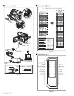
Communication cable
Connect the Communication cable between the PC cable and
Jig connector cable when performing a PC adjustment.
•
Jig connector cable
Connected to JIG CONNECTOR of the main board and used
for electrical adjustment, etc.
•
Conversion connector
Conversion connector is used to convert the connector part of
the JIG connector cable.
4.2
JIG CONNECTOR CABLE CONNECTION
4.2.1 CAUTIONS
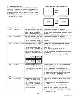
(1) Only 9 of 30pins of JIG CONNECTOR CABLE(PN:YTU93106B)
are extended with wires. Additional 5pins (3,6,7,11and18)
need to be soldered and extended with the wires for adjust-
ment and checking.
See Fig. 4-2-1 for details.
Fig.4-2-1
: ADDITIONAL WIRE
7
13
22pin CVF_G
23pin CVF_B
24pin COM_VF
25pin FS_PLL
26pin HID
27pin MAIN_VCO
28pin IF_RX
29pin AL_3VSYS
30pin NOT USE
8pin XSTH
9pin GND
5pin NOT USE
13pin IF_TX
12pin ENV_OUT
10pin GND
7pin CVF_R
24
28
25
27
29
<COMPONENT SIDE>
<FOIL SIDE>

