1-14 (No.YF124)
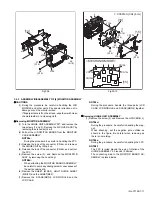
3.2.5 ASSEMBLY/DISASSEMBLY OF [9] VF ASSEMBLY
z
Before disassembly
As the VF ASSEMBLY has complicated structure, do not dis-
assemble if not needed.
When assembling, be careful to prevent dust or any foreign
materials entering inside, and avoid soils on both the LENS
and the SHEET.
z
Disassembly procedure
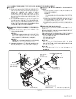
(1) Remove the screw (1), and then remove the KNOB
(SWITCH).
(2) Remove the screw (2), and remove the BKT.(COVER).
(3) Pull out the CASE(VF) from the VF ASSY, remove the
screw (3), and then remove the EYE CUP.
(4) Remove the two screws (4, 5), and then remove the
COVER(EYE CUP).
NOTE9a:
Do not remove the COVER(EYE CUP) if not needed
as the CASE(VF) can be removed without removing
the COVER(EYE CUP).
(5) Peel off the FPC, and then remove the CASE(VF).
NOTE9b:
During the procedure, be careful in handling the FPC.
(6) Set the LEVER(VF) to the TRIANGLE MARK( ) of the
CASE(VF), and then remove the LENS ASSY.
NOTE9c:
During the procedure, be careful in handling the parts.
Pay special attention not to damage, soil, or leave fin-
gerprints on the surface.
NOTE9d:
After attaching the LENS ASSY, rotate the LE-
VER(VF) counterclockwise to check the smooth slid-
ing operation of the LENS ASSY.
(7) Press hooks (L9c,d) on both sides of the HOLDER(LCD)
to remove the LCD SA from the CASE(VF).
NOTE9e:
During the procedure, be careful not to damage the VF SW.
NOTE9f:
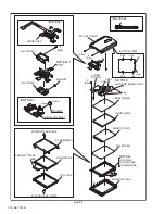
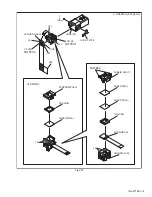
Refer to the Fig.(VF2) for the disassembly of the LCD
SA, and disassemble the LCD SA if necessary. During
the procedure, be careful to prevent dust or any for-
eign materials entering inside.
(8) Remove the FPC from the connector (CN9), and then re-
move the VF BOARD ASSY.
NOTE9g:
During the procedure, be careful not to damage the parts.
Fig.VF1
0.069N
m(0.7kgf
cm)
b
b
b
a
a
TRIANGLE MARK( )
MARKING
<NOTE9d>
<NOTE9b>
LEVER(VF)
CASE(VF)
LENS ASSY
COVER(SLIDE)
COVER(EYE CUP)
BKT.(COVER)
KNOB(SWITCH)
EYE CUP
L9a
L9a
L9b
1
(S9a)
3
(S9c)
4
(S9d)
5
(S9d)
2
(S9b)
NOTE9c


