background image

20

To set the other convenient functions, use menus.
You can use the buttons either on the remote control or on
Monitor for menu operations.
• Refer also to “Menu Classifications” on pages 26 and 27.

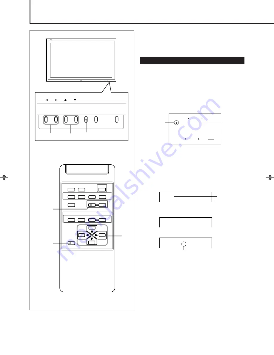
Showing On-screen Display

The input mode and signal type will be indicated on the
screen.
• The following procedure can be done by using the buttons

on the Monitor. You can also show these information by
pressing DISPLAY on the remote control. (See page 12.)

1

Press MENU (or MENU/EXIT on the
remote control) to display the Main
Menu.

2

Press 

5

/

 to move the cursor (

3

) to

“STATUS DISPLAY.”

3

Press 

3

 to display the current input

terminal and received signal type.

Note:

• If you want to make these information appear automatically

when you change the input mode, see “Showing the On-
screen When Changing the Input Mode” on page 22.

MENU INPUT

POWER

MENU INPUT

POWER

MENU

2

 / 

3


5

5

 / 

Other Convenient Functions

DISPLAY

ASPECT

POWER

RGB

COMPO.

VIDEO B

VOLUME

MULTIPLE

MODE

ID SET

MONITOR ADJUSTMENT

VIDEO A

MUTING

MENU/EXIT

RM-C575 REMOTE CONTROL UNIT

ID

MENU/EXIT

VOLUME –

2

 / 

3

5

 /  

5

S I Z E / P O S I T I O N       A D J .
P I C T U R E       A D J .
F U N C T I O N   S E L E C T
S T A T U S   D I S P L A Y

E N T E R :

M A I N   M E N U

S E L E C T :

E X I T :

M E N U

This item
appears only
when the
“RGB” input is
selected.

Cursor (

3

)

V I D E O   A
N T S C

C O M P O N E N T
4 8 0 i

P C
3 7 . 9 k H z             6 0 . 3 H z *

Input selected

Input Video signal
type

Ex. When selecting “COMPONENT” input

Ex. When selecting “RGB” input

When the signal being input is a preset video
mode, an “*” will be shown after the
frequency.

Ex. When selecting “VIDEO A” input

20-23.GD-V4200PZW-A[EN]/f

00.2.23, 5:20 PM

20

Summary of Contents for GD-V4200PCE

Page 1: ...rations 24 Connecting the Remote Control Cables 24 Assigning ID Numbers 24 Operating the Monitors Simultaneously 25 Operating the Monitors Individually 25 Menu Classifications 26 Main Menu 26 Setup Menu 27 Troubleshooting 28 Self diagnostic Indication 29 Specifications 30 Contents This instruction manual refers to the GD V4200PZW GD V4200PZW G GD V4200PCE and GD V4200PCE G The explanations and ill...

Page 2: ...n engineered and manufactured to assure your personal safety But IMPROPER USE CAN RESULT IN POTENTIAL ELECTRICAL SHOCK OR FIRE HAZARD In order not to defeat the safeguards incorporated into this product observe the following basic rules for its installation use and service Please read these Important Safeguards carefully before use All the safety and operating instructions should be read before th...

Page 3: ...oints or short out parts that could result in a fire or electric shock Never spill liquid of any kind on the product Do not attempt to service this product yourself as opening or removing covers may expose you to dangerous voltages and other hazards Refer all service to qualified service personnel Unplug this product from the wall outlet and refer service to qualified service personnel under the f...

Page 4: ...ns to set IDs etc when serial connection is made DISPLAY ASPECT POWER RGB COMPO VIDEO B VOLUME MULTIPLE MODE ID SET MONITOR ADJUSTMENT VIDEO A MUTING MENU EXIT RM C575 REMOTE CONTROL UNIT ID 1 7 8 9 p q 2 4 3 5 6 6 MENU EXIT button Use this button to display or erase menus While a sub menu is displayed pressing this button will move you one screen back to the preceding menu 7 Remote control cable ...

Page 5: ...buttons to adjust the volume level 4 MENU button Use this button to display or erase menus While a sub menu is displayed pressing this button will move you one screen back to the preceding menu 5 INPUT button page 12 Use this button to switch between inputs Only for GD V4200PCE and GD V4200PCE G Only RGB input can be reproduced Though you can switch to the other inputs the images will not reproduc...

Page 6: ...120 230V SPEAKER OUT I IN OUT INTERNAL EXTERNAL 1 2 3 4 5 6 AUDIO PC AUDIO VIDEO AUDIO VIDEO AUDIO VIDEO VIDEO B COMPONENT RGB VIDEO A Y L MONO L MONO R R Y C Y C PB B Y PR R Y L MONO R IN OUT IN OUT L MONO R R L Monitor Rear View Parts Identification Continued GD V4200PZW and GD V4200PZW G only ...

Page 7: ...GB AUDIO To input video S video component and audio signals you need to install video interface kit IF C420P1W which is separately purchased 1 RS 232C CONTROL Input terminal D sub 9 pin page 11 Connect this terminal to the RS 232C terminal of a personal computer For the control method using this terminal consult an authorized JVC dealer 2 AC INPUT terminal page 11 Connect the supplied power cord t...

Page 8: ... causing a fire injury etc or dirtying the vicinity Take notice of the following Do not mix old and new batteries Do not mix different types of battery as different types may have different characteristics Place the batteries according to the ª and markings indicated on the battery compartment When installing the batteries insert the end first to avoid a short circuit Use only the specified batter...

Page 9: ... same image pattern to be continuously displayed on the screen for a long time otherwise the area on the screen corresponding to the image may vary in brightness leaving an afterimage on the screen To reduce the afterimage you can use the White Back function see page 22 The Monitor is manufactured using very high precision technology allowing for more than 99 99 active pixels however be aware that...

Page 10: ...56 4 Non interlace 2 VGA400 70 640 400 31 5 70 1 Non interlace 3 VGA480 60 640 480 31 5 59 9 Non interlace 4 VGA480 72 640 480 37 9 72 8 Non interlace 5 VGA480 75 640 480 37 5 75 0 Non interlace 6 MAC13 640 480 35 0 66 7 Non interlace 7 SVGA 56 800 600 35 2 56 3 Non interlace 8 SVGA 60 800 600 37 9 60 3 Non interlace 9 SVGA 72 800 600 48 1 72 2 Non interlace 10 XGA 60 1024 768 48 4 60 0 Non interl...

Page 11: ... control the Monitor Remote control cable supplied When using external speakers set this to EXTERNAL To speaker input terminals Hi vision equipment DVD etc VCR To audio output terminals To video output terminals External Speakers Power cord supplied To a wall outlet To audio output terminals To monitor output terminal To S video output terminal To video output terminal Connecting a VCR A VCR can a...

Page 12: ...s set to EXTERNAL no sounds come out of the built in speakers When you want to hear audio sound from the built in speakers set the INTERNAL EXTERNAL selecting switch to INTERNAL To turn off the volume immediately Press MUTING MUTING ON is displayed and the sound goes out Pressing the button again resumes the previous volume level To make the screen indication appear Press DISPLAY The types of inpu...

Page 13: ...watching programs using a wide screen mode for a while will reduce the burn in gradually With this Monitor you can select among three types of wide screens FULL ZOOM and PANORAMIC in addition to the REGULAR screen of conventional 4 3 aspect ratio Press ASPECT to select the screen size Each time you press the button the screen size changes as follows REGULAR Displays at conventional 4 3 aspect rati...

Page 14: ...nately to adjust to the appropriate size 1 Press MENU EXIT or MENU on the Monitor to display the Main Menu 2 Press 5 to move the cursor 3 to SIZE POSITION ADJ 3 Press 3 to display the Size Position Adjustment Menu 4 Press 5 to move the cursor 3 to the item you want to adjust Item Adjustment range H horizontal SIZE 80 to 80 H POSITION 80 to 80 V vertical SIZE 80 to 80 V POSITION 80 to 80 CLOCK PHAS...

Page 15: ... move the cursor 3 to reset 2 Press 3 The confirmation screen appears 3 Press 3 again to reset the adjustments To cancel the reset press MENU EXIT or MENU on the Monitor Note Adjustment values for both horizontal and vertical sizes of the screen are so related that if one is adjusted up to near the maximum value the attainable value of the other will be decreased 0 1 H S I Z E H SIZE H POSITION V ...

Page 16: ...ake an adjustment while viewing the adjustment bar After step 3 on page 15 proceed as follows 1 Press 5 to move the cursor 3 to sub menu 2 Press 3 to display the Sub Menu The Sub Menu for CONTRAST appears on the screen 3 Press 5 to select the Sub Menu you want to adjust Each time you press the button the Sub Menu changes as follows 4 Press 2 3 to adjust the selected item 5 Repeat steps 3 and 4 to ...

Page 17: ...r temperature alternate between HIGH and LOW HIGH To make the screen become bluish LOW To make the screen become reddish 6 Press MENU EXIT or MENU on the Monitor twice to exit from the menu operations To reset the setting You can only reset the color temperature aspect ratio see page 18 and video signal type see page 19 at the same time See Resetting the Function Selection Menu Settings on page 19...

Page 18: ...e the cursor 3 to ASPECT 5 Press 2 3 to select an aspect ratio you want Each time you press the button the aspect ration changes as follows For detailed information on these aspect ratios see page 13 6 Press MENU EXIT or MENU on the Monitor three times to exit from the menu operations To reset the setting You can only reset the color temperature see page 16 aspect ratio and video signal type see p...

Page 19: ...T EXIT M E N U This item appears only when the RGB input is selected Cursor 3 Resetting the Function Selection Menu Settings You can reset all the following Function Selection Menu settings at a time Colour Temperature see page 16 Aspect Ratio see page 18 Receivable Signal Types SIGNAL MODE see the left column 1 Press MENU EXIT or MENU on the Monitor to display the Main Menu 2 Press 5 to move the ...

Page 20: ...nformation appear automatically when you change the input mode see Showing the On screen When Changing the Input Mode on page 22 MENU INPUT POWER MENU INPUT POWER MENU 2 3 5 5 Other Convenient Functions DISPLAY ASPECT POWER RGB COMPO VIDEO B VOLUME MULTIPLE MODE ID SET MONITOR ADJUSTMENT VIDEO A MUTING MENU EXIT RM C575 REMOTE CONTROL UNIT ID MENU EXIT VOLUME 2 3 5 5 S I Z E P O S I T I O N A D J ...

Page 21: ...rming the Use Time You can confirm the hours of use on the Setup Menu This may be necessary when you ask for any service 1 On the remote control Press MENU EXIT while holding VOLUME to display the Setup Menu On the Monitor Press MENU while holding 2 to display the Setup Menu 2 Confirm the hour of use The displayed value for the hours of use is divided by 100 To calculate the actual hours of use mu...

Page 22: ...peat steps 1 and 2 then select OFF by pressing 2 3 Showing the On screen When Changing the Input Mode With this function you can see the selected input mode and signal type when changing the input mode 1 On the remote control Press MENU EXIT while holding VOLUME to display the Setup Menu On the Monitor Press MENU while holding 2 to display the Setup Menu 2 Press 5 to move the cursor 3 to STATUS DI...

Page 23: ...ove the cursor 3 to SCREEN SAVER 3 Press 2 3 to select the desired setting Each time you press the button the Screen Saver function alternates between ON and OFF To cancel the Screen Saver function select OFF 4 Press MENU EXIT or MENU on the Monitor twice to exit from the menu operations Cursor 3 P O W E R S A V E C O N T R O L L O C K S T A T U S D I S P L A Y S C R E E N S A V E R W H I T E B A ...

Page 24: ...Master Monitor screen MASTER is displayed and 00 is displayed on all of Slave Monitor screens 3 Press ID SET On the Slave Monitor screens 01 02 03 and so on will be displayed in the order of connection Notes When a maximum number of 20 Monitors are connected it will take approx 10 seconds for ID numbers to be displayed on all the screens If 00 is displayed on all the Monitor screens or if some of ...

Page 25: ...rm any desired operations such as adjusting menu items Notes If 00 is displayed on all the Monitor screens or if some of the Monitor screens have no indication in step 1 press MODE to turn off the indications on all screens and then press MODE again If the ID number of the Monitor selected in step 2 is not highlighted or if the ID numbers of more than one Monitor are highlighted press MODE to clea...

Page 26: ... G H T C H R O M A P H A S E S H A R P N E S S s u b m e n u r e s e t A D J U S T P I C T U R E A D J S E L E C T E X I T M E N U V I D E O A 0 1 0 2 0 0 0 0 0 0 Main Menu Size Position Adjustment Menu Picture Adjustment Menu Function Selection Menu Status Display 0 1 C O N T R A S T 0 1 B R I G H T 0 1 C H R O M A 0 1 P H A S E 01 SHARPNESS 0 1 H SIZE 01 H POSITI ON 01 V SIZE 0 1 V P O S I T I O...

Page 27: ... VIDEO A or B terminal Setup Menu POWER SAVE Sets the length of time before standby mode is automatically assumed after the input signal has stopped being supplied See page 21 CONTROL LOCK Sets the Monitor so that it cannot be operated with the buttons on itself See page 21 STATUS DISPLAY Sets if you want the input terminal and the type of signal to be indicated on the screen just after inputs are...

Page 28: ...ug firmly Turn on the MAIN POWER switch Select the correct input by pressing VIDEO A VIDEO B COMPO and RGB on the remote control or INPUT on the Monitor Connect connected devices correctly Set connected devices correctly Check if the signal is appropriate scanning frequency etc and input the appropriate signal Adjust brightness on the menu Adjust volume Refer to Self diagnostic indication and take...

Page 29: ...all your dealer and tell which lamps are lighting or flashing Copy and fax the Self diagnostic Report Sheet below Note If you turn on the Monitor soon after turning it off or after recovering from a brief power interruption the self diagnostic lamps may light or flash and no image may appear on the screen In this case turn off the Monitor again wait for about 10 seconds then turn it on again If no...

Page 30: ...x 1 1V p p 75Ω Video output BNC terminal x 1 1V p p 75Ω Audio input Pin jack terminal x 2 L R 500mV rms 22kΩ or over VIDEO B Y C input Y C terminal x 1 Y 1V p p 75Ω C 0 286V p p 75Ω for NTSC C 0 3V p p 75Ω for PAL SECAM Video input BNC terminal x 1 1V p p 75Ω Video output Pin jack terminal x 1 1V p p 75Ω Audio input Pin jack terminal x 2 L R 500mV rms 22kΩ or over COMPONENT input BNC terminal x 3 ...

Page 31: ...minal Pin number Signal name 1 Red 2 Green 3 Blue 4 N C 5 GND 6 GND 7 GND 8 GND Pin number Signal name 9 N C 10 GND 11 GND 12 N C 13 H SYNC 14 V SYNC 15 N C External GND 1 2 3 4 5 6 7 8 9 10 11 12 13 14 15 Dimensions Side view Front view Top view 4 3 2 1 9 8 5 7 6 MENU INPUT POWER 1035 40 4 3 89 3 8 5 57 5 2 8 3 570 22 2 1 17 16 11 997 39 8 3 940 37 8 1 921 36 8 3 640 25 4 1 577 22 4 3 518 4 20 2 ...

Page 32: ...32 ...

Reviews: