background image

(No.PA037<Rev.001>)1-5

1.5

Preventing static electricity

Electrostatic discharge (ESD), which occurs when static electricity stored in the body, fabric, etc. is discharged, can destroy the laser
diode in the traverse unit (optical pickup).  Take care to prevent this when performing repairs.

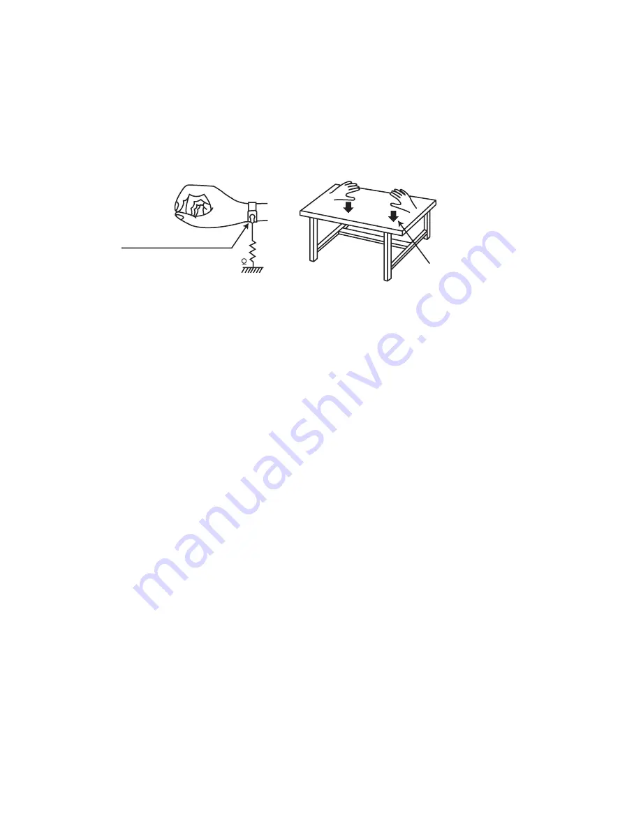
1.5.1  Grounding to prevent damage by static electricity

Static electricity in the work area can destroy the optical pickup (laser diode) in devices such as laser products. 
Be careful to use proper grounding in the area where repairs are being performed. 

(1) Ground the workbench

Ground the workbench by laying conductive material (such as a conductive sheet) or an iron plate over it before placing the
traverse unit (optical pickup) on it.

(2) Ground yourself

Use an anti-static wrist strap to release any static electricity built up in your body.      

1.6

INSTALLATIONS

1.6.1 Installation method

The D-ILA system (reflecting type active matrix liquid crystal system) does not require convergence adjustment. Note the following
when placed on a floor (refer to OPERATING INSTRUCTIONS for actual operating method).

(1) Place the projector at the position needed for the required image size observe the projector is not tilted horizontally. 

[The image size is 60 to 200(wide side) inches diagonal (16:9), requiring a projection distance of 1.78m to 6.06m]

(2) Adjust the placement site and screen tilt so that the projection angle is perpendicular to the screen.
(3) Adjust the placement site and screen position (height) so that the projection lens center is at the lower edge of the screen.
(4) Project an image on the screen. (Connect video equipment and power source, switch power on and select the input.)
(5) Fine adjust the projected image position and angle. If adjusting the placement site and screen cannot correct the projected po-

sition (too low) or angle (lower part of image widened), adjust the front foot.

(6) Turn the lens ZOOM ring by hand and adjust for suitable image size.
(7) Turn the lens FOCUS ring by hand and adjust to correct image blur.

1.6.2 Installation site and status

• The projector contains a fan for cooling. Obstruction of the ventilation openings can lead to internal overheating, abnormal operation

and failure. Also observe there is plenty of free space between the projector and adjacent walls, ceiling and other equipment. 
Note that excess heat can cause failure and damage to both the projector and nearby equipment.

 Required spacing :

Front = 15cm / left and right sides = 30cm / rear = 20cm (When the unit is enclosed with block according to the required spacing
on the left side, provide the unit with adequate ventilation so that the temperature inside of the enclosed area is kept at the same
temperature in the open space in the room.)

• Avoid locations that are wobbly or inclined. If the setting site floor has protrusions or horizontal cannot be maintained, there is risk

the projector may drop, fall over, etc. If located in a site where left to right tilt is greater than ±5

°

 and front to rear tilt greater than

±10

°

, particularly the optical system components can be severely affected and there is risk basic performance and quality of the

projector cannot be maintained.

• Observe the site can stably bear the weight (approx. 11.0kg) of the projector over a long period of time.
• If mounted on a stand with casters, observe the casters are securely braked to prevent movement.
• Avoid suspending in a location subject to vibration. Both the projector and mounting fixture can be damaged.
• Do not place in the following types of locations.

Especially, Avoid locations subject to dust, grit, smoke or other airborne contaminants. Use adequate caution when providing exter-
nal ventilation, filters and dust protection.

1M

Conductive material
(conductive sheet) or iron palate

(caption)
Anti-static wrist strap

‹

Near water or in humid sites

‹

Near heaters or heat generating equipment

‹

Dust or grit

‹

Direct sunlight

‹

Oily or tobacco smokes

‹

Very high or very low temperature

Summary of Contents for DLA-HD550-BC

Page 1: ...RVICE MANUAL DLA HD550 BU DLA HD550 BC DLA HD550 BE DLA HD550 WE DLA HD950 BU DLA HD950 BC DLA HD950 BE DLA HD990 BU DLA HD990 BE COPYRIGHT 2010 Victor Company of Japan Limited TABLE OF CONTENTS 1 PRECAUTION 1 4 2 SPECIFIC SERVICE INSTRUCTIONS 1 6 3 DISASSEMBLY 1 14 4 ADJUSTMENT 1 19 5 TROUBLESHOOTING 1 22 for DLA HD950 HD990 ...

Page 2: ... Part No BHL5010 S BHL5010 SC CHINA mod el Average lifespan 3000 hours normal mode Screen Size Approx 60 to 200 Aspect ratio 16 9 Projection Distance Approx 1 8m to 12m Color System NTSC NTSC4 43 PAL PAL M PAL N SECAM Auto Manual switch Analog Video Input Format 480i 480p 576i 576p 720p 50Hz 720p 60Hz 1080i 50Hz 1080i 60Hz Digital Video Input Format 480i 480p 576i 576p 720p 50Hz 720p 60Hz 1080i 50...

Page 3: ... 525 640 480 2 VGA 72 640 X 480 37 900 72 000 31 500 832 520 640 480 3 VGA 75 640 X 480 37 500 75 000 31 500 840 500 640 480 4 VGA 85 640 X 480 43 300 85 000 36 000 832 509 640 480 5 SVGA 56 800 X 600 35 200 56 000 36 000 1024 625 800 600 6 SVGA 60 800 X 600 37 900 60 000 40 000 1056 628 800 600 7 SVGA 72 800 X 600 48 100 72 000 50 000 1040 666 800 600 8 SVGA 75 800 X 600 46 900 75 000 49 500 1056...

Page 4: ...ne jack control shafts etc to be sure the product is safe to operate without danger of electrical shock Do not use a line isolation transformer during this check Plug the AC line cord directly into the AC outlet Using a Leakage Current Tester measure the leakage current from each exposed metal parts of the cabinet particular ly any exposed metal part having a return path to the chassis to a known ...

Page 5: ...nt foot 6 Turn the lens ZOOM ring by hand and adjust for suitable image size 7 Turn the lens FOCUS ring by hand and adjust to correct image blur 1 6 2 Installation site and status The projector contains a fan for cooling Obstruction of the ventilation openings can lead to internal overheating abnormal operation and failure Also observe there is plenty of free space between the projector and adjace...

Page 6: ...t native contrast ratios Innovations such as these and many other superb features en able the DLA HD950 to achieve an exceptionally high native contrast ratio of 50 000 1 Enhanced brightness extended white peak and deeper rich er blacks wide dynamic range ensure image reproduction that is vivid and full of depth making these projectors perfectly suited for viewing diverse content such as movies an...

Page 7: ... Standby mode Light on Green During projection Blinking Green Image is temporarily hidden Blinking Red Cool Down mode Blinking Red Green Adjust mode Light on Light on Lamp replacement is near The LED lights when the lamp is used more than 2900 hours The Lamp replacement message appears on the screen when the unit is turned on Lamp cover is not put on No projection due to a non lighting lamp Lamp b...

Page 8: ...n mode To turn on off the power To switch input To hide the image temporarily Left button To display the menu To return to the previous menu Down button Up button Right button Power input terminal Power input terminal S video terminal S video terminal Composite video terminal Composite video terminal RS 232C terminal RS 232C terminal TRIGGER terminal Component video terminals Component video termi...

Page 9: ... The STAND BY and LAMP LEDs alternately flash for about 3 seconds then only the STAND BY LED lights steadily RESET AFTER REPLACING PROCESSOR PWB ASS Y The lamp use time data are stored in memory on the PRO CESSOR PWB ASS Y and need to be reentered after replac ing the PROCESSOR PWB ASS Y Use the special software and a personal computer to reenter the data Afterwards con firm the mode has been retu...

Page 10: ...65261U9 Unit exchange OPTICAL BLOCK ASSY DLA HD550 PC0072001U9 Inc DD PWB Unit exchange OPTICAL BLOCK ASSY DLA HD950 PC0072002U9 Inc DD PWB Unit exchange OPTICAL BLOCK ASSY DLA HD990 PC0072003U9 Inc DD PWB Unit exchange LAMP UNIT DLA HD550 950 990 BE BU BHL5010 S Unit exchange LAMP UNIT DLA HD550 950 BC BHL5010 SC Unit exchange EXHAUST FAN 80MM PC0065220U9 Unit exchange EXHAUST FAN 92MM PC0065219U...

Page 11: ...ill go out of the screen NOTE The SERVICE MENU will go out of the screen automatically after 10 seconds if you do not press the MENU button MENU BACK Back Exit Soft Ver Adjust Model Main Sub DD Location Option Operate Select Soft Version Screen MENU BACK Back Exit Soft Ver Adjust Color Temp 6500K Lens Aperture 1 Off Option Operate Select Adjust Screen DLA HD550 MENU BACK Back Exit Soft Ver Adjust ...

Page 12: ...ontal Red Horiz Green 1 7 4 Adjust REGI Pixel shift of Horizontal Green Horiz Blue 1 7 4 Adjust REGI Pixel shift of Horizontal blue Vert Red 1 5 3 Adhust REGI Pixel shift of Vertical Red Vert Green 1 5 3 Adjust REGI Pixel shift of Vertical Green Vert Blue 1 5 3 Adjust REGI Pixel shift of Vertical Blue Colour Mangement Natural Different in the picture mode Stage Different in the picture mode Dyamic...

Page 13: ...20 0 0 65 0 0 0 SCE Yellow_Range 55 0 0 10 0 0 0 SCE Yellow_Gain 10 0 0 65 0 0 0 SCE Green_Range 60 0 0 10 0 0 0 SCE Green_Gain 20 0 0 65 0 0 0 SCE Cyan_Range 60 0 0 10 0 0 0 SCE Cyan_Gain 20 0 0 65 0 0 0 SCE Blue_Range 60 0 0 10 0 0 0 SCE Blue_Gain 20 0 0 65 0 0 0 SCE Magenta_Range 60 0 0 10 0 0 0 SCE Magenta_Gain 20 0 0 65 0 0 0 Natural Cinema1 Cinema2 Cinema3 Stage Dynamic THX User1 User2 Contr...

Page 14: ... side remove the three screws C attaching the Top cabinet See Fig 3 Fig 3 2 Remove the two screws D attaching the both side of the Top cabinet See Fig 4 3 Disengage four hooks a engaged both side of the Top cab inet See Fig 4 Fig 4 4 Remove the one screw E attaching hte connector wire See Fig 5 5 Disconnect the connector wire from main body connected to connector CN1 of the Operation PWB See Fig 5...

Page 15: ...onnect the connector wire from main body connected to connector J1 of the IP PWB See Fig 11 3 Disconnect the connector wires from Front cover connect ed to connectors CN1906 and CN1907 of the Pricessor PWB See Fig 11 Fig 11 3 1 6 Removing the IR PWBs See Fig 12 1 Remove the two screws J attaching the IP PWBs Fig 12 3 1 7 Removing the Fan control PWB See Fig 13 14 1 Remove the three screws K attach...

Page 16: ... from Power supply PWB and then remove the five screws N attaching the Power supply PWB See Fig 16 Fig 16 3 1 9 Removing the Processor PWB See Fig 17 18 19 1 Disconnect the each connector wires from Processor PWB and then remove the six screws P attaching the Shield cov er See Fig 17 Fig 17 2 Peal the terminal sheet and then remove the two screws Q two screws R and four screws S attaching the Proc...

Page 17: ...1 3 Remove the three screws W attaching the Optical block See Fig 22 Fig 22 3 1 11 Removing the Air duct Upper See Fig 23 1 Remove the seven screws X attaching the Air duct Up per Fig 23 3 1 12 Removing the Temp sensor PWB See Fig 24 1 Remove the one screw Y attaching the Tem sensor PWB Fig 24 3 1 13 Removing the Ballast PWB See Fig 25 1 Remove the three screws Z attaching the Ballast PWB Fig 25 U...

Page 18: ...Exhaust fan the label of Exhaust fan put on the vent When attach the Exhaust fan plate installed by 92mm fan please cove in the slit of the sponge 3 1 16 Removing the Lamp cover switch PWB See Fig 27 1 Remove the one screw CC attaching the Lamp cover switch PWB Fig 27 3 1 17 Removing the Thermostat See Fig 28 1 Remove the two screws DD attaching the Thermostat Fig 28 3 1 18 Removing the AC inlet S...

Page 19: ... raster pattern 10 HDTV signal generator component output Y PB PR HDMI output Flat raster pattern 50 100 Closs hatch 4 3 REQUIRED ADJUSTMENTS BY REPLACING COMPONENTS The following adjustment procedure is required after replacing PWB ASS Ys and OPTICAL BLOCK 4 3 1 COMPONENT REQUIRED ADJUSTMENT AT REPLACING Note 1 When EEPROM backup is not possible adjust COLOR TEMPERATURE 4 3 2 LIST OF REQUIRED INS...

Page 20: ...tocol 6 Click ACR2 in Color Management Control 7 Select Cinema1 from Select Bank and then click Re ceive All to transfer data from the projector Perform the same procedure to save Cinema2 3 and THX 8 Click FCT in Color Management Control 9 Select Natural from Select Bank and then click Receive All to transfer data from the projector 10 Click File Save to save the CSV file in the PC Perform the sam...

Page 21: ...e 5800 50 Deviation 0 0 05 6500K Color temperature 6500 50 Deviation 0 0 05 7500K Color temperature 7500 50 Deviation 0 0 05 9300K Color temperature 9300 50 Deviation 0 0 05 4 4 6 PIXEL SHIFT ADJUSTMENT 1 Input color cross hatch signal 2 From the Service menu set Adjust to Pixel Shift 3 Adjust H Pixel Adj R H Pixel Adj B to make H direction Pixel Shift to become the best point 4 Adjust V Pixel Adj...

Page 22: ... Lamp section 90 C The WARNING LED turns on Thermal sensor IC Set interior Lamp area TENP PWB ASS Y 70cC The WARNING LED turns on Thermal sensor IC Set exterior Filter area PROCESSOR PWB ASS Y 51 C The WARNING LED turns on Motor operation de tection circuit Cooling fan Cooling fan interior Fan stop Power off by main CPU emergency mode Type Monitor objective Location Operating point Function Interl...

Page 23: ...button and delete all data stored in projector z ERROR LOG SCREEN ITEMS z POWER STATUS 0 Stand by mode 1 Power on mode 2 Cooling mode 4 Emergency mode ERROR CODE SETUP NUMBER LAMP TIME Min SYSTEM TIME Min OUTSIDE TEMPERATURE INSIDE TEMPERATURE POWER STATUS NOT USED F1 17 568 1840 42 44 1 00 00 No Item Detected condition 1 Error code 01 No projection caused by the lamp failure 03 Error of IIC data ...

Page 24: ...x exe It uses it for the installation of the update tool 5 5 2 Installation procedure of an installation file ILAFPJ_Updater_for_HDxxx_Vx x exe CAUTION Ii is condition not to connect a projector and please perform the installation 1 Put an installation file in the suitable place and open by double click The window of the chart below appears 2 Installation Wizard Click a Next button four times in t...

Page 25: ...it from the place of a list or the indication 4 Check Search the most suitable driver at the next place 5 CHeck off the Removal media 6 Check Include the next place refer the installer folder Default is C Program Files ILA FPJ Updater 7 Cclick Next and install it 5 5 4 HOW TO USE THE UPDATE TOOL 1 Set the projector to UP DATE mode While pressing Stand by On button then plug the power cord ALL LED ...

Page 26: ...rror code Category Message 1 10 USB con nection Projector was not found 2 3 11 4 5 20 Header check Firmware file is broken 6 21 7 22 8 30 Model check Projector model does not match between the firmware and your projector 9 31 10 40 Burning flash Failed to update the firmware 11 41 12 42 13 43 14 44 15 45 16 46 17 47 18 48 19 49 20 50 Get Version Failed to get version information 21 51 22 52 23 53 ...

Page 27: ... No PA037 Rev 001 1 27 ...

Page 28: ...37 Rev 001 VSE Printed in Japan Victor Company of Japan Limited Digital Imaging Products Business Division Projector Operation 12 3 chome Moriya cho Kanagawa ku Yokohama city Kanagawa prefecture 221 8528 Japan ...

Reviews: