background image

30

Connecting to Various Devices 

DLA-M2000LU/M2000SCU/ LCT0940-002A / ENGLISH

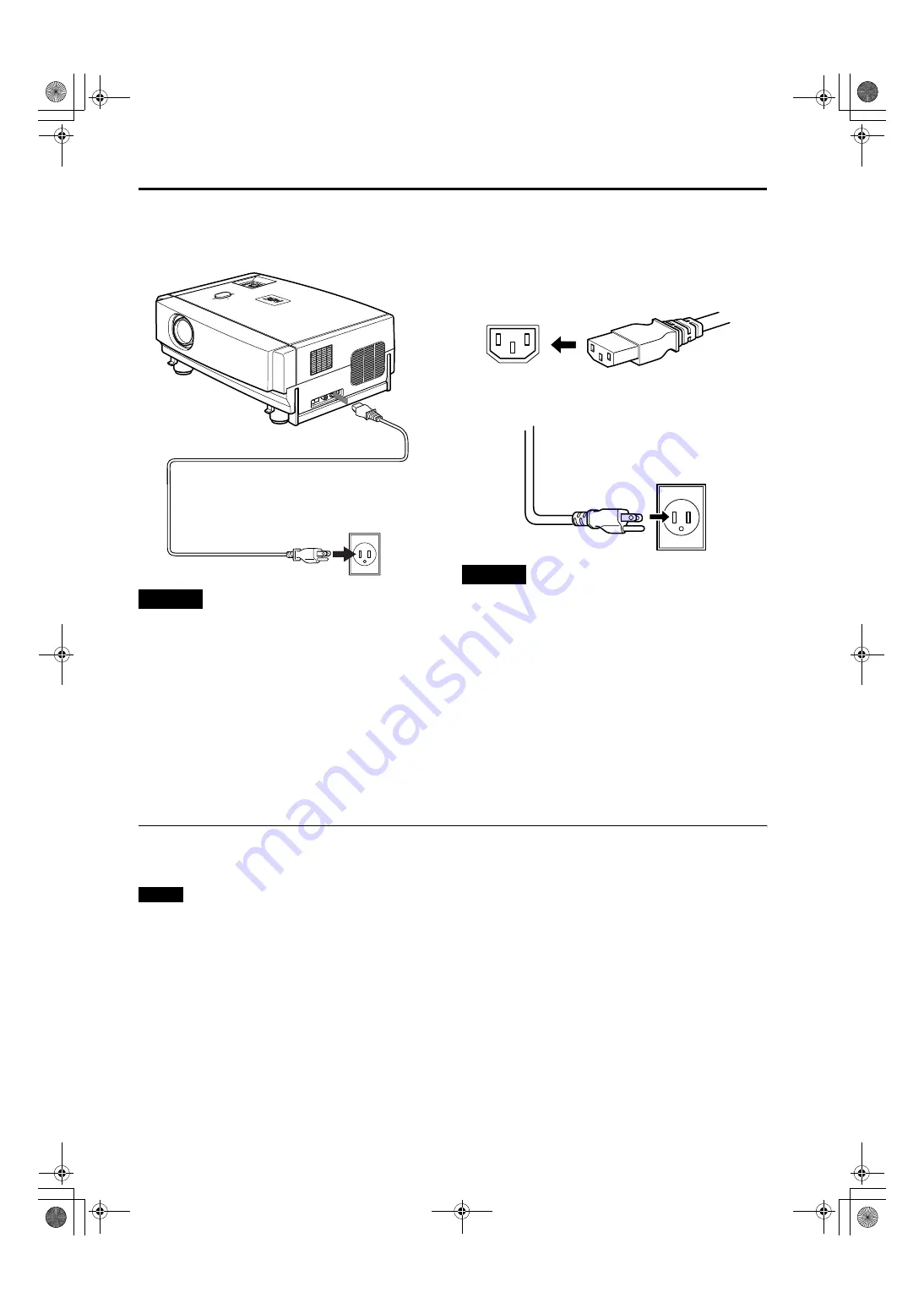
Connecting the Power Cord

After all devices have been finished being connected, connect the supplied power cord. At this time, 

do not yet turn on the 

MAIN POWER switch

.

CAUTIONS

To prevent fire and electric shock, observe the 
following:

• When you do not use devices, pull out their power cords 

from wall outlets.

• Do not connect the devices with power cords other than 

those supplied.

• Do not use mains voltage other than the power voltage 

indicated.

• Do not scar, damage, or work on the power cords. Also, do 

not put a heavy object on, heat, or stretch the power cords, 
otherwise they may be damaged.

• Do not insert or pull out the plugs with a wet hand.

1

Insert the supplied power cord into the 
power input terminal of the projector.

2

Insert the main plug of the supplied 
power cord into a suitable wall outlet.

CAUTIONS

• Do not turn on the projector without installing the lens unit 

(optional). Doing so can cause the lens-hole blind cover 
(black one) initially installed to be deformed by heart from 
the light-source lamp.

• Since the power requirement of the projector is high, insert 

the power plug directly into a wall outlet.

• Use the supplied power cord with the ferrite core only.
• Do not remove the ferrite core from the supplied power 

cord; Otherwise, there may be a possibility that a harmful 
interference occurs.

Removing the Lens Cap

Remove the lens cap before using the projector.

Notes

• The lens cap is supplied with the lens unit (optional). It 

should be attached to the lens when the projector is not 
used.

• Do not operate the projector with the lens cap attached. 

Doing so can deform the lens cap because of the heat. A 
metallic lens cap can get hot and cause injury.

LA

MP

TE

MP

HID

E

PC

VID

EO

ME

NU

KE

YS

TO

NE

VO

LU

ME

PR

ES

ET

ES

CA

PE

EN

TE

R

OP

ER

A T

E

Power cord (supplied)


Summary of Contents for D-ILA DLA-M2000SCU

Page 1: ...ENGLISH FRANÇAIS PROJECTOR MANUEL D INSTRUCTIONS PROJECTEUR DLA M2000LU DLA M2000SCU INSTRUCTIONS EN T E R Lenses are optional ...

Page 2: ... DLA M2000LU M2000SCU LCT0940 002A ENGLISH INSTRUCTIONS PROJECTOR DLA M2000LU DLA M2000SCU Thank you for purchasing this projector Before using it read and follow all instructions carefully to take full advantage of the projector s capabilities ...

Page 3: ...nd or table The product may fall causing serious injury to a child or adult and serious damage to the product The product should be mounted according to the manufacturer s instructions and should use a mount recommended by the manufacturer When the product is used on a cart care should be taken to avoid quick stops excessive force and uneven surfaces which may cause the product and cart to overtur...

Page 4: ... other hazards Upon completion of any service or repairs to this product ask the service technician to perform safety checks to determine that the product is in proper operating condition The product should be placed more than one foot away from heat sources such as radiators heat registers stoves and other products including amplifiers that produce heat When connecting other products such as VCR ...

Page 5: ...ns Cap 30 Basic Operations 31 1 Turning on the Power 31 2 Select the Input source to be Projected 32 3 Adjust the Screen Size Zooming 32 4 Adjust Focus 33 5 Adjusting Sound Volume 33 Turning off Image and Sound HIDE 34 Removing the Trapezoidal Distortion of the Image 34 Quick Alignment Function QUICK ALIGN 35 Displaying a Still Picture FREEZE 36 Zooming a Part of the Image DIGITAL ZOOM 36 Menu Ope...

Page 6: ...trol unit RM M2000G AA R6 size dry cell battery 2 for checking operation Power cord approx 8 2 ft approx 2 5 m Hex wrench Personal computer connection cable approx 6 56 ft approx 2 m D sub 3 row 15 pin Type QAM 0104 002 AV connection cable approx 6 56 ft approx 2 m Type QAM 0303 001 Remote cable approx 9 84 ft approx 3 m 3 5 mm dia stereo mini plug Type QAM 0363 001 Conversion adapter for Mac for ...

Page 7: ...MAIN POWER switch This is the main power switch When it is turned on the projector goes into stand by state and the STAND BY indicator on the control panel comes on Refer to page 31 ON The main power turns on OFF The main power turns off 6 Adjustable feet for adjusting the height and angle By extending the feet the projector angle can be adjusted up to 7 For details refer to Adjusting the Inclinat...

Page 8: ...r details refer to Connector Panel on page 11 e Rear adjustable foot for leveling the projector It is set at the shortest position when shipped from the factory Turn the foot to make the projector level Adjustment can be made in the range of 1 5 and 1 5 from the horizontal position For details refer to Adjusting the Inclination of the Projector on page 16 r Air inlet This is the air inlet Do not c...

Page 9: ...ilter reduces the cooling effect causing heat to build up inside which could cause a fire or malfunction u Opening for replacing the light source lamp For replacing the light source lamp refer to Replacing the Light Source Lamp on page 56 i Fixing foot o Position selecting screw for ceiling mounting When using the projector in an upside down ceiling mounted position inverted top to bottom and righ...

Page 10: ...icator is blinking Even if you press the OPERATE button the projector is not turned on Wait until the projector enters stand by mode STAND BY indicator stays lit 4 PC button Use this button to select a device connected to the PC 1 or PC 2 terminals Each time you press the button the selection alternates between PC 1 and PC 2 PC1 or PC2 will be displayed on the top right of the projected image This...

Page 11: ...is button only works for the keystone setting screen q KEYSTONE buttons Use these buttons to correct a trapezoidal distortion of the projected image Refer to page 34 w HIDE button Use this button to turn off the image on the screen and audio sound temporarily Pressing it again restores the image and audio sound to resume Refer to page 34 e VOLUME buttons Use these buttons to adjust the sound volum...

Page 12: ... 15 pin This is the terminal for video output from the monitor of the computer connected to PC1 or PC2 The computer input signal projected on the screen is output A display monitor can be used by connecting it to this terminal 8 PC computer 2 input terminals BNC 5 These are multipurpose video input terminals that allow input of the following signals Analog RGB signals vertical sync V signals and h...

Page 13: ...ils refer to Basic Menu Operation on page 42 5 PC button Use this button to select a device connected to the PC 1 or PC 2 terminals Each time you press the button the selection alternates between PC 1 and PC 2 Refer to page 32 PC 1 or PC 2 will be displayed on the top right of the projected image This function can be disabled using the menu 6 VIDEO button Use this button to select a device such as...

Page 14: ... of the projected video image The focus point becomes more distant The focus point becomes nearer t VOLUME buttons Use these buttons to adjust the sound volume Increase the volume level 0 50 Decrease the volume level 50 0 Refer to page 33 y QUICK ALIGN Quick Alignment button Use this button to automatically align Horizontal and vertical position Tracking and Phase for the projected image During th...

Page 15: ...gs Beware of the following Do not mix new and old batteries Do not mix different types of batteries as they differ in characteristics Place batteries so they match the polarities indicated to and to Be sure to put the minus end in first to avoid short circuiting Use only designated batteries Remove the batteries if the remote is not to be used for a prolonged period When the batteries are exhauste...

Page 16: ...range 20 to 80 no condensation Allowable storage temperature range 14 F to 140 F 10 C to 60 C When installing the projector observe the following Do not use the projector placed on its side Avoid using the projector placed on its side This could cause a malfunction Use the projector within the specified angle Do not use the projector inclined 30 horizontally left right This could cause color varia...

Page 17: ...oth sides upward raise the projector The adjustable feet automatically extend To retract the feet push the levers and lower the projector slowly the projector is fixed at the position where you release the levers Leveling the projector Lift the projector rotate the rear adjustable foot and adjust the horizontal angle until the projector is level Y PB B Y PR R Y H V G B R AUDIO REMOTE PC AUDIO RS 2...

Page 18: ...ctor has a function to correct the trapezoidal distortion of the projected image on the screen To correct this distortion use the KEYSTONE buttons on the projector Refer to Removing the Trapezoidal Distortion of the Image on page 34 Also correction is possible by using the Keystone menu Refer to Setting and Adjusting Other Functions OPTIONS on page 52 LAMP TEMP STAND BY HIDE PC VIDEO MENU KEYSTONE...

Page 19: ... screen directly the picture tends to become pale and dim Use a curtain or other means to shield the light Set the projector horizontally on a surface that is within the range of adjustable angles up down adjustment angle 7 horizontal adjustment angle 1 5 If the keystone is adjusted the projected screen becomes smaller When hanging from the ceiling use a dedicated hanging fixture not supplied Opti...

Page 20: ...he cap on the top of the projector to open it 2 Loosen the SHIFT LOCK fixing bolt Use the hex wrench supplied 3 Rotate the LENS SHIFT knob to adjust the position shift amount of the projected screen Rotate it to the right The lens shifts upward Rotate it to the left The lens shifts downward 4 Tighten the SHIFT LOCK fixing bolt firmly Use the hex wrench supplied 5 Turn the cap to close it Projected...

Page 21: ...ote cable between the wired terminal of the remote control unit and the REMOTE terminal on the rear of the projector Connect the plug which has the remote cable core to the projector unit remote terminal Using it as a wired remote control you do not have to worry about the operative angle of the unit though the operative distance is limited by the length of the remote cable approx 9 84 ft approx 3...

Page 22: ...ounting Turn the screw counterclockwise To ceiling mount and adjust the projector special expertise and technique are necessary Be sure to ask your dealer or a specialist to perform this work To turn the position selecting screw for ceiling mounting use a Philips screwdriver with a 30 mm or longer shank The screw is located in the hole shown in the illustration Note When using the projector in a c...

Page 23: ...input to the Y PB B Y PR R Y 10 input terminals 10 To use these signals it is required to set the PC2 BNC item in the submenu Options 1 to YPBPR Refer to page 52 Computer signals Signals with the following scanning frequencies can be input to the PC 1 or PC 2 G B R H CS V terminals Be sure that the computer to be used suffices the following conditions The computer has the video signal output port ...

Page 24: ...s Vertical resolution Ver Lines Horizontal frequency H kHz Vertical frequency V Hz PC system PC98 VESA350 640 350 37 86 84 13 PC AT PC98 640 400 24 83 56 42 DOS V VGA 60Hz 640 480 31 47 59 94 VGA 72Hz 640 480 37 86 72 81 VGA 75Hz 640 480 37 50 75 00 VGA 85Hz 640 480 43 27 85 01 SVGA 56Hz 800 600 35 16 56 25 SVGA 60Hz 800 600 37 88 60 32 SVGA 72Hz 800 600 48 08 72 19 SVGA 75Hz 800 600 46 88 75 00 S...

Page 25: ...put the sound signal to the AUDIO terminal of the AV IN terminals Memo When connecting a video device use a TBC along with it or one which has a built in TBC Use of an extension cable to connect a video device and the projector could cause video degradation When a signal with much jitter is reproduced on a VCR or special effect playback is performed the upper part of the image or the image itself ...

Page 26: ...minal is used PC2 BNC must be selected from the menu options Refer to Setting and Adjusting Other Functions OPTIONS on page 52 When the image signal is input to the PC2 input terminal input the sound signal to the PC AUDIO terminal Memo Other devices with component signal output terminals DVD player NTSC etc can be connected DVD Digital Video Disc DTV format signals 480i 480p 720p 1080i can be inp...

Page 27: ...s to be connected Read thoroughly the manual that comes with the device to be connected Use the supplied AV connection cable or the cable supplied with the game device Y PB B Y PR R Y H V G B R AUDIO REMOTE PC AUDIO RS 232C Y C VIDEO Cable supplied with the game device or supplied AV connection cable Game device etc To AUDIO To VIDEO BNC RCA conversion plug accessory To AV IN ...

Page 28: ... on page 69 For further details consult your dealer or an authorized service center The supplied remote control can be used as a wired remote control Use the supplied remote cable to connect the REMOTE terminal of the main unit with the wired remote control terminal of the remote control Refer to page 20 Y PB B Y PR R Y H V G B R AUDIO REMOTE PC AUDIO RS 232C Y C VIDEO EN T E R HIDE OPERATE PRESET...

Page 29: ...Refer to Setting and Adjusting Other Functions OPTIONS on page 52 Y PB B Y PR R Y H V G B R AUDIO REMOTE PC AUDIO RS 232C Y C VIDEO POWER Desktop type To PC 1 Personal Computer connection cable supplied To monitor connector To R To G To B Notebook type There are some notebook types which do not allow the computer s LCD to work if an external display is connected With such a notebook computer the L...

Page 30: ...al computer connection cable and the supplied conversion adapter for Mac Notes When connecting an audio output terminal such as a computer sound source to the projector connect to the PC AUDIO terminal using the separately available audio cable Other connections are the same as in the connection example for IBM PC or IBM compatible PCs Y PB B Y PR R Y H V G B R AUDIO REMOTE PC AUDIO RS 232C Y C VI...

Page 31: ...f the supplied power cord into a suitable wall outlet CAUTIONS Do not turn on the projector without installing the lens unit optional Doing so can cause the lens hole blind cover black one initially installed to be deformed by heart from the light source lamp Since the power requirement of the projector is high insert the power plug directly into a wall outlet Use the supplied power cord with the ...

Page 32: ...0 seconds Note The OPERATE button will not work for approximately 1 minute from when the light source lamp is turned on Use the button after approximately 1 minute 2 Turn off the MAIN POWER switch after the STAND BY indicator changes to steady on OFF The MAIN POWER switch turns off and the STAND BY indicator goes off CAUTION Do not turn off the MAIN POWER switch during cool down mode the STAND BY ...

Page 33: ...utton it is necessary to reconnect the audio cable to the active device since the projector has only a single AUDIO input terminal When the PC1 or PC2 input terminal signal source is switched with the PC button it is necessary to reconnect the audio cable to the active device since the projector has only a single PC AUDIO input terminal When no image signal is input to the selected input terminal ...

Page 34: ...ue 0 to 50 When 15 sec is displayed in the menu Audio Vol will appear in approximately 15 seconds When you press the VOLUME button The sound volume becomes higher 0 50 When you press the VOLUME button The sound volume becomes lower 50 0 When the volume is set to 0 no sound will be heard from the built in speaker Notes When Audio Vol is displayed on the screen pressing the PRESET button resets the ...

Page 35: ...verted trapezoid form is corrected as shown in the figure To cancel correction and restore the original screen press the PRESET button Adjusted value 0 Press the ESCAPE button to immediately remove the keystone display Notes The trapezoidal distortion keystone can be adjusted from the option menu Refer to page 52 The range of the trapezoidal distortion adjustment is approximately 20 in the vertica...

Page 36: ...s input from the PC1 or PC2 input terminals It does not work for the signals input from the AV IN terminal VIDEO or Y C input terminal The quick alignment function is used to automatically adjust the Horizontal and vertical position Phase and Tracking of the projected image When using the quick alignment function to automatically adjust the image use a bright still picture It may not function corr...

Page 37: ...m appears on the screen together with the level bar and magnifying power 1 0 1 2 1 4 1 6 2 0 2 5 3 2 4 0 When 15 sec is displayed in the menu Digital zoom will appear in approximately 15 seconds To zoom up or zoom down press the DIGITAL ZOOM or button on the remote control Moving the zoomed image While Digital zoom appears on the screen you can move the zoomed image with the cursor 5 2 3 ENTER but...

Page 38: ...ers the stand by mode 15 30 60 OFF PC2 BNC RGB or YPBPR Set to RGB when a computer device with analog RGB V H Cs signals is connected to the PC2 terminals Set to YPBPR when a device with component signals Y B Y R Y or DTV format signals Y PB PR are connected to the PC2 terminals Language Language for on screen display Japanese English German Spanish Italian French Information Input Shows the termi...

Page 39: ...tions Language Information Input Switcher Source Lamp time VIDEO CH 0 NTSC 123 h Language Options 2 Right Left rev Top Bottom inv RS 232C bps Sleep time min Options 1 OFF OFF 9600 ENTER ON ON 19200 15 30 60 OFF English Deutsch Español Italiano Français Press 5 to select an item Press 2 3 to set or adjust the value 3 or ENTER You can see the information Main menu in Video Menu Mode Press 5 to selec...

Page 40: ...55 the adjustable range varies depending on signals G Gain Adjusts the green leve 0 to 255 the adjustable range varies depending on signals B Gain Adjusts the blue leve 0 to 255 the adjustable range varies depending on signals All reset Reset above items to the factory set values Yes No Options Refer to page 52 Options 1 Menu display 15sec Menu disappears in 15 seconds ON Menu stays on Line displa...

Page 41: ...requency H Frequency V Lamp time PC 1 CH 0 1280 1024 79 9 75 123 kHz Hz h Language Options 2 Right Left rev Top Bottom inv RS 232C bps Sleep time min Options 1 OFF OFF 9600 ENTER ON ON 19200 15 30 60 OFF English Deutsch Español Italiano Français Keystone 0 12 12 Press 5 to select an item Press 2 3 to set or adjust the value 3 or ENTER Press 5 to select an item Press 2 3 to select Yes or No Then pr...

Page 42: ...es Yes No Options Refer to page 52 Options 1 Menu display 15sec Menu disappears in 15 seconds ON Menu stays on Line display 5sec Line display such as PC1 or PC2 appears on top right of the screen for 5 seconds when the VIDEO or PC button is pressed OFF Line display does not appear Keystone Press ENTER to enter the Keystone submenu Keystone Adjust to correct the trapezoidal distortion of the projec...

Page 43: ...selected in step 2 is displayed on the screen When you selected Information in step 2 no submenu is available 4 Press the cursor button 5 or to select an item in the submenu When a Language has been selected in step 2 press to set the language 5 Press the cursor button 2 2 2 2 or 3 3 3 3 to set or adjust the value When an item which has the ENTER message has been selected in step 4 press the ENTER...

Page 44: ...ESCAPE DIGITAL ZOOM KEYSTONE PC VIC SELECT MENU FREEZE VIDEO RM M2000 REMOTE CONTROL UNIT MENU button ENTER button Cursor buttons 5 2 3 PRESET button ESCAPE button LAMP TEMP STAND BY HIDE PC VIDEO MENU KEYSTONE VOLUME PRESET ESCAPE ENTER OPERATE MENU button ENTER button Cursor buttons 5 2 3 PRESET button ESCAPE button Menu Image adj Setting Color temp Options Language Information Brightness Contra...

Page 45: ...ing 1 submenu appears on the screen 3 Select Decoder with the cursor button 5 or and press the ENTER button The Decoder submenu appears on the screen Video submenus 4 Set the color system with the cursor button 5 or AUTO Normally set to AUTO Factory set value The color system of a video signal being input is automatically identified and displayed in In B W Black White NTSC NTSC4 43 PAL or SECAM wi...

Page 46: ... format Video Menu Mode Only 1 Press the MENU button The main menu appears on the screen 2 Select Setting with the cursor button 5 or and press 3 3 3 3 or the ENTER button The Setting 1 submenu appears on the screen 3 Select Setting 2 with the cursor button 5 or and press 3 3 3 3 or the ENTER button The Setting 2 submenu appears on the screen 4 Select Screen or HDTV with the cursor button 5 or 5 A...

Page 47: ...ubmenu appears on the screen Video submenu PC submenu 3 Select Tracking or Phase with the cursor button 5 or Phase is shown only in PC submenu 4 Adjust the tracking or phase with the cursor 2 2 2 2 or 3 3 3 3 Adjust the tracking and phase of the picture image being projected To adjust the phase first check for correct tracking adjustment To adjust multiple items repeat 3 and 4 5 Press the ESCAPE b...

Page 48: ...appears on the screen Press the cursor button 2 to select Yes and then press the ENTER button All items in the Image adj submenu are reset to the factory set values and the menu returns to the previous one To exit the All reset submenu without performing All reset select No with the cursor button 3 and press the ENTER button To be continued on the next page Image adj Brightness Contrast Sharpness ...

Page 49: ...increases image becoming blueish 5 Select R Gain or G Gain or B Gain with the cursor button 5 or 6 Fine adjust the color temperature with the cursor button 2 2 2 2 or 3 3 3 3 To adjust multiple items repeat 5 and 6 To perform All Reset In the Color temp submenu select All reset with the cursor button 5 or and press the ENTER button Then the All reset submenu appears on the screen Press the cursor ...

Page 50: ... screen position display position can be adjusted Menu The menu position can be adjusted 5 Press the cursor button 5 5 5 5 2 2 2 2 or 3 3 3 3 to move the video screen display or the menu Repeat 4 and 5 to move both video screen display and menu positions Factory set value 6 Press the ESCAPE button to return to the previous menu or press the MENU button to exit the menu mode Setting 1 Position Tone...

Page 51: ...ctory set value 5 Press the ESCAPE button to return to the previous menu or press the MENU button to exit the menu mode Adjustment item Button Adjustment content Tone 2 or 3 The image tone projected on the screen can be changed TV Suitable for projecting the video programs Cinema Suitable for projecting the cinema programs Aspect change 2 or 3 Sets the vertical to horizontal ratio 4 3 or 16 9 of t...

Page 52: ...Select Resize with the cursor button 5 5 5 5 or 4 Choose 1 1 Panel or Aspect with the cursor button 2 2 2 2 or 3 3 3 3 5 Press the ESCAPE button to return to the previous menu or press the MENU button to exit the menu mode Changing the Clamp pulse position PC Menu Mode Only When the image is too dark or bright or when the image is unstable switching the position may improve the image quality Norma...

Page 53: ... the Keystone submenu To enter the Options 2 submenu select Options 2 with the cursor button 5 or and press the ENTER button To return to the Options 1 submenu from the Options 2 submenu select Options 1 with the cursor button 5 or and press the ENTER button To adjust multiple items repeat 3 to 4 To reset the keystone trapezoidal distortion of the picture image to the original setting press the PR...

Page 54: ...ay Keystone ENTER Press the ENTER button to enter the keystone submenu In the keystone submenu press 2 or 3 to correct trapezoidal distortion of the projected image 80 0 128 To reset the keystone trapezoidal distortion of the picture image to the original setting factory set value 0 press the PRESET button when the Keystone submenu appears on the screen To exit the keystone submenu press the ESCAP...

Page 55: ...te that it is not being used Source Shows the projected image s type of video signal Video menu mode Resolution Shows the resolution of the video signal being received PC menu mode It may not be displayed correctly with some input signals Frequency H Shows the horizontal frequency of the video signal being received PC menu mode Frequency V Shows the vertical frequency of the video signal being rec...

Page 56: ...pe 15A 250V Otherwise a fire may occur and or the projector may be damaged 1 Turn off the main power switch and disconnect the power cord from both the projector and the wall outlet In stand by state the STAND BY indicator lights on place the MAIN POWER switch of OFF position 2 Loosen the fuse holder to remove it To loosen the fuse holder use a Philips screwdriver 3 Remove the fuse from the fuse h...

Page 57: ...ore before performing replacement Before starting light source lamp replacement work turn off the MAIN POWER switch and disconnect the power cord from the wall outlet If you perform the replacement work with the power cord connected this could cause injury or electric shock The light source lamp used in this projector is a high pressure mercury lamp Be careful when disposing of the light source la...

Page 58: ...screws with a flat end screwdriver Note The screws are fitted so that they do not come off the lamp replacement opening cover 2 Loosen the screws raise the handle and pull out the light source lamp Loosen the two screws with a flat end screwdriver Note The screws are fitted so that they do not come off the light source lamp To be continued on the next page Screw Lamp replacement opening cover Be c...

Page 59: ...ndle a new light source lamp hold it by the plastic part Never touch the metal part or the front glass surface 4 Replace the lamp replacement opening cover and fasten the screws Fasten the two screws with a flat end screwdriver CAUTIONS Install the light source lamp and close the lamp replacement opening cover correctly otherwise a safety switch is activated to prevent the projector from operating...

Page 60: ... stays on Buttons must be pressed within 2 seconds of the previous button When you make a mistake in button operations return to the beginning of the sequence To check the lamp time on the menu press the MENU button and select Information with the cursor button 5 or The lamp use time is indicated in the item Lamp time Video main menu PC main menu CAUTION Reset the lamp use time only when you have ...

Page 61: ...dirt etc the projector goes into an warning state the OPERATE and STAND BY indicator blink etc Therefore regularly clean the filter For the warning indication refer to page 64 3 Clean the filter Clean the filter with a neutral detergent wash it in water and then dry it in the shade CAUTIONS Put on rubber gloves when using neutral detergent After you have washed the filter in water make sure the fi...

Page 62: ...e or exhaust area blocked Turn off the MAIN POWER switch remove any blocking objects and turn on the MAIN POWER switch again 6 7 31 Video image does not appear or audio sound does not occur Is the correct input selected Select the correct input with the VIDEO and PC buttons 9 12 13 Are devices connected correctly Connect devices correctly 11 22 Are signals being supplied from the connected devices...

Page 63: ...quality color density etc adjusted correctly Adjust picture quality on the menu 47 Is the correct color system selected Set the color system to AUTO or to the correct dedicated color system 44 Are signals scanning frequency etc of the connected devices appropriate Check if the signal is appropriate scanning frequency etc and input the appropriate signal 22 Is the PC2 input terminal being used When...

Page 64: ...eps 1 Turn off the MAIN POWER switch and unplug the power cord from the wall outlet 2 Take an action according to the number No 4 Set the filter in place Then leave the projector until it cools down No 5 Check that nothing is blocking the air inlet nor outlet and wait until the inside cools down No 6 Check that nothing is blocking the air inlet nor outlet and wait until the inside cools down No 7 ...

Page 65: ...video signal is within the acceptable range other items such as resolution are out of the projector s specifications The selected input mode input terminal name is shown in the first line of the message Input the video signals that satisfies the projector s specifications 22 23 66 When the FREEZE button is pressed this message appears for a few seconds When a button not acceptable is pressed durin...

Page 66: ...not work for the inputted video signals To use the this function input the video signals that can be digitally zoomed 12 36 The accumulated lamp use time reaches 900 hours Every time the projector is turned on this message appears on the screen Press the ESCAPE button to clear the massage This display can be cleared with the MENU button or other buttons Arrange for a new light source lamp or repla...

Page 67: ...Automatic switching manual switching Resolution 1365 dots 1024 dots S XGA full resolution during RGB input 1000 TV lines Horizontal resolution aspect ratio 4 3 during video input Scanning frequency Horizontal frequency 15 kHz 105 kHz Vertical frequency 50 Hz 100 Hz Audio power output 1 W monaural 1 5 8 4 cm round type micro speaker 1 AV IN Y C 1 line mini DIN 4 pin 1 for S video VIDEO 1 line BNC 1...

Page 68: ...rademark of the non profit organization Video Electronics Standards Association All other product names mentioned herein are used for identification purposes only and may be the trademarks or registered trademarks of their respective companies Outside dimensions Top Front Side Power requirements 120 V AC 60 Hz Power consumption 9 A Allowable operation temperature 41 F to 95 F 5 C to 35 C Allowable...

Page 69: ...4 Pin number Signal name 1 GND Y 2 GND C 3 Y 4 C 2 3 4 5 6 7 1 8 9 Pin number Signal name Pin number Signal name 1 N C 6 N C 2 RD 7 N C 3 TD 8 N C 4 N C 9 N C 5 GND 1 2 3 4 5 6 7 8 9 10 11 12 13 14 15 Pin number Signal name Pin number Signal name 1 Red 9 N C 2 Green 10 GND SYNC 3 Blue 11 GND 4 N C 12 N C 5 N C 13 H SYNC 6 GND Red 14 V SYNC 7 GND Green 15 N C 8 GND Blue ...

Page 70: ...ojector When sending a control command use the following data format Header Designates the head of data and the kind of data 21h Control command to the projector 3Fh Query to the projector Asking command ID 1 fixed SP Designates the delimiter for ID Command and Parameter 20h CR Designates the terminal of the data 0Dh is not necessary when Asking command 2 2 Response data format from the projector ...

Page 71: ...ers 3 Control command table The control commands that can be sent from the computer are as follows Keystone Numeric value can range from FF80 to 0080 Operation mode Only Asking command is possible Character Hex Meaning 0 30 OFF 1 31 ON Character Hex Meaning 0 30 Y C 1 31 VIDEO 3 33 PC1 4 34 PC2 Character Hex Meaning 0000 30h 30h 30h 30h Stand by mode 0001 30h 30h 30h 31h Power on mode 0002 30h 30h...

Page 72: ...0 approx 330 2 cm 8 53 2 60 9 32 2 84 140 approx 355 6 cm 9 22 2 81 10 04 3 06 150 approx 381 0 cm 9 88 3 01 10 79 3 29 160 approx 406 4 cm 10 56 3 22 11 52 3 51 170 approx 431 8 cm 11 22 3 42 12 24 3 73 180 approx 457 2 cm 11 88 3 62 12 96 3 95 190 approx 482 6 cm 12 57 3 83 13 68 4 17 200 approx 508 0 cm 13 22 4 03 Projection screen size Diagonal length Approximate projection distance unit ft m ...

Page 73: ... 0 cm 44 09 13 44 48 03 14 64 400 approx 1016 0 cm 50 36 15 35 54 86 16 72 450 approx 1143 0 cm 56 63 17 26 61 65 18 79 470 approx 1193 8 cm 59 12 18 02 64 37 19 62 480 approx 1219 2 cm 60 37 18 40 500 approx 1270 0 cm 62 89 19 17 521 approx 1323 3 cm 65 52 19 97 Projection screen size Diagonal length Approximate projection distance unit ft m For 4 3 aspect ratio screens For 16 9 aspect ration scr...

Reviews: