background image

No. 51955

AV42PD20ES

26

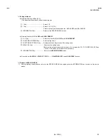
Setting item

Colour system

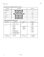
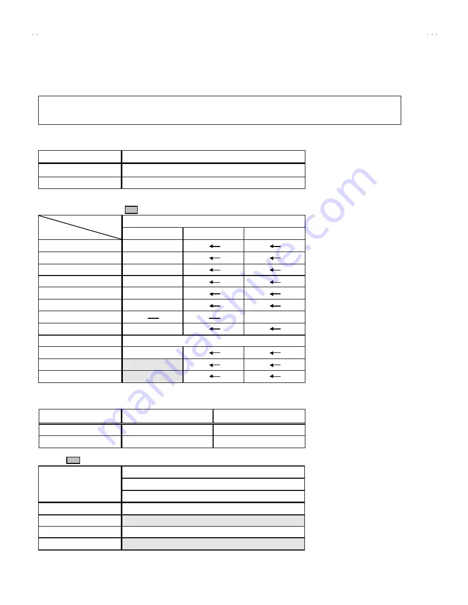
INITIAL SETTING VALUE OF SERVICE MENU

1.  Ad justment of the SERVICE MENU is made on the basis of the initial setting values ; however, the new setting values which

set  the screen  in its  optimum  condition may differ from the initial  setting.

2.  Do  no t change the initial setting values of the setting (Adjustment) items not listed in “ ADJUSTMENT”.

1.IF

SETTING ITEM

Initial setting value

1.VCO

Proper value by adjustment.

See “adjustment of VCO” contents

2.ATT ON/OFF

Do not adjust this item.

2.V/C (VIDEO / CHROMA)   

(        is adjustment not to required )

Initial setting value

PAL

SECAM

NT SC


1. R. GAIN

-15


2. G. GAIN

-15


3. B. GAIN

-15


4. BRIGHT

20


5. CONT RAST

0


6. COLOUR

-10


7. HUE

011


8. SHARP

0


9. VCO ADJUSTMENT

Automatic ally optimized  after adjustment


10. VIDEO AGC

00


11. SYNC SL ICE

+07


12. A. MOVIE

01

3.AUDIO (Do not adjust)

Setting item

Variable range

Initial setting value

(Fixed value)

1. ERR LIMIT

00H

FFH

10

2. A2 ID THR

00H

FFH

19

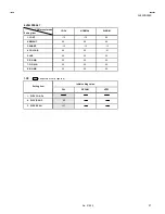
4.DEF  

(      is adjustment not to required )

VALUE

FULL

Setting item

50Hz p


1. V-SHIFT

-03


2. V-SIZ E

00


3. H-CENT

-06


4. H-SIZE

00

Summary of Contents for AV42PD20ES

Page 1: ...ICATIONS 2 SAFETY PRECAUTIONS 4 WARNING 5 FEATURES 6 FUNCTIONS 7 TECHNICAL INFORMATION 9 INSTALLATIONS 11 SPECIFIC SERVICE INSTRUCTIONS 12 SERVICE ADJUSTMENTS 21 TROUBLESHOOTING 36 PARTS LIST 37 OPERATING INSTRUCTIONS STANDARD CIRCUIT DIAGRAM 2 1 SERVICE MANUAL PLASMA WIDE TELEVISION BASIC CHASSIS MF ...

Page 2: ...5 7cm Measured diagonally Speaker 8cm round 2 16cm round 1 sub woofer 4Ω Audio Output Rated 5W 5W L R 20W sub woofer Antenna Input 75Ωunbalanced Coaxial EXT 1 21 pin Euro connector SCART socket Video Audio L R RGB signal input are available TV broadcast output Video and Audio L R are available EXT 2 21 pin Euro connector SCART socket S Video Video Audio L R RGB signal input are available AV select...

Page 3: ...O input 19 VIDEO output 1V P P Negative going sync 75Ω TV LINE OUT NC 20 VIDEO Y input 1V P P Negative going sync 75Ω only VIDEO input 21 COMMON GND 15 PIN D SUB CONNECTOR PC IN connector Each type signal of computer Model Resolution Horizontal Frequency kHz Vertical Frequency Hz IBM PC AT 640 480 31 5 59 9 compatible VGA 37 9 72 8 37 5 75 0 43 3 85 0 51 1 100 4 61 3 120 4 800 600 35 2 56 3 SVGA 3...

Page 4: ... lead dress Extra precaution should be given to assure correct lead dress in the high voltage circuit area W here a short circuit has occurred those components that indicate evidence of overheating should be replaced Always use the manufacturer s replacement components 7 Isolation Check Safety for Electrical Shock Hazard After re assembling the product always perform an isolation check on the expo...

Page 5: ... are identified in the Parts List of Service Manual Electrical components having such features are identified by shading on the schematics and by on the Parts List in the Service Manual The use of a substitute replacement which does not have the same safety characteristics as the recommended replacement part shown in the Parts List of Service Manual may cause shock fire or other hazards 4 The lead...

Page 6: ...njoy music programs and sporting events with live realism In addition BILINGUAL programs can be heard in their original language Built in ECO ECONOMY ECOLOGY sensor MODE In accordance with the brightness in a room the brightness and or contrast of the picture can be adjusted automatically to make the optimum picture which is easy on the eye Users can make VCR dubbing of picture and sound by contro...

Page 7: ...AME 1PC IN CONNECTOR 15pin D sub connector 2HEADPHONE JACK MINI JACK 3EXIT 4 TERMINAL 4VOLUME BUTTON Press this button to display the volume level indicator Press the up down buttons to change volume while the volume level indicator is displayed 5 UP DOWN BUTTONS You can use this button as the buttons of the PR channel Pressing the volume button makes this button function as the volume buttons 2 3...

Page 8: ... Key 4 HYPER SOUND Key 5 INFORMATION Key 6 TV Key 7 VOLUME Key 8 STAND BY Key POWER 9 PIP Key A COLOUR Key B TEXT Key C MENU OK Key D PR CHANNEL UP DOWN Key E FUNCTION Key F MODE Key F T L LIST FLOF TOP G HOLD Key H SUB PAGE Key I STORE Key J SIZE Key K REVERSAL Key L INDEX Key M DISPLAY CANCEL Key N TV TEXT DVD Key O CHANGE Key P FREEZE Key Q SUB PAGE Key i i ...

Page 9: ...G B colour The size of a cell is 0 36mm horizontally and 1 08mm vertically PIXEL FAULT There are two pixel faults bright fault and dark fault that are respectively defined as follows 1 BRIGHT FAULT In this pixel fault a cell that should not light originally is lighting or flashing on and off For checking this pixel fault input ALL BLACK SCREEN and find out the cell that is lighting or flashing on ...

Page 10: ...n level 100 on entire screen Dark fault Blue level 100 on entire screen A zone 3 or less than 3 in each colour B zone 8 or less than 8 in each colour 2 or Less than 2 consecutively Note A zone Center portion area enclosed by 1 4 vertically from the top and bottom and 1 4 horizontally from the right and left sides B zone Other area Note The consecutive pixel fault that are diagonally or intensively...

Page 11: ...age the inner circuit 2 Install a PDP in a place where is well ventilated Ambient temperature should be within a range of 0 40 3 Install in not dusty place If dust covers the air intake holes inside ventilation effect will reduce Then it may damage the inner circuit If the unit uses in such atmosphere it will strongly require regular cleaning or maintenance 2 REQUIREMENTS FOR SETTING The following...

Page 12: ...l discharge of the lighted portion is more activated than the non lighted portions resulting in higher brightness 3 This unit has functions such as PIXEL SHIFT COLOUR REVERSE and REFRESH They will reduce burning Please refer to the instruction book for detail 3 INFRARED RAYS Because the near infrared rays 800 1000mm radiate from the panel face the neighboring infrared ray remote controllers infrar...

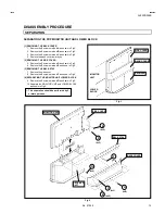
Page 13: ...e 3 screws marked D as shown in Fig 2 6 Remove the 2 screws marked E as shown in Fig 2 3 REMOVING THE BACK STAY 7 Remove the side cover 8 Remove the 2 screws marked F as shown in Fig 2 4 SEPARATING THE MONITOR UNIT LOWER BLOCK 9 Remove the 2 screws marked G as shown in Fig 2 10 Separate the MONITOR UNIT and LOWER BLOCK as shown in Fig 2 This separation should be performed by 2 or more persons Fig ...

Page 14: ...emove the 4 screws marked H L R as shown in Fig 5 3 As shown Fig 5 remove the under panel L R in the arrow direction marked I 5 REMOVING THE FRONT CONTROL PWB Take out the RECEIVER UNIT 4 Remove the 3 2 1 screws marked A as shown in Fig 5 5 Remove the 6 screws marked B on the FRONT CONTROL PWB as shown in Fig 5 If necessary take off the wire clamp connectors etc 6 REMOVING THE SPEAKER NET CENTER P...

Page 15: ... 4 CHASSIS CASE RECEIVER UNIT CASE COVER A 10 B 6 C 2 AV PLATE CHASSIS BEAM Fig 5 SW LEVER FONT SW PWB SPEAKER NET R SPEAKER NET L SUB WOOFER SPEAKER SPEAKER L R UNDER PANEL L UNDER PANEL R FRONT CONTROL PWB E 4 C 2 C 2 D 1 D 1 2 1 A B 6 F 4 I 4 TOP CENTER PANEL I H H 2 2 G ...

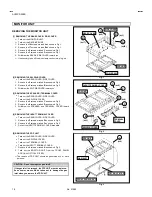
Page 16: ...rked D as shown in Fig 2 3 Withdraw the SPEAKER and TERMINAL COVER toward you 4 REMOVING THE INPUT TERMINAL COVER Take out the REAR COVER SIDE COVER 1 Remove the 5 screws marked E as shown in Fig 2 2 Remove the 2 screws marked F as shown in Fig 2 3 Pull out the INPUT TERMINAL COVER backward 5 REMOVING THE PDP UNIT Take out the REAR COVER SIDE COVER Take out the SW PWB COVER Take out the TERMINAL C...

Page 17: ... of Fig 2 will be displayed 4 Check the setting values of the SYSTEM CONSTANT SET of Table 1 If value is different select the setting item with the FUNCTION key and set the correct value with the FUNCTION key 5 Press the MENU OK keyto memorize the setting value 6 Press the INFORMATION key and return to the normal screen 5 Setting of receive channels Set the receive channel For setting refer to the...

Page 18: ... 2 ATT Do not adjust 4 DEF 1 V SHIFT 2 V SIZE 3 H CENT 4 H SIZE 2 V C 1 R GAIN 2 G GAIN 3 B GAIN 4 BRIGHT 5 CONTRAST 6 COLOUR 7 HUE 8 SHARP Don t move 9 VCO ADJUSTMENT 10 VIDEO AGC Don t move 11 SYNC SLICE Don t move 12 A MOVIE Don t move 5 VSM PRESET COOL NORMAL WARM 1 CONT 2 BRIGHT 3 SHARP 4 COLOUR 5 HUE 6 R GAIN 7 G GAIN 8 B GAIN 3 AUDIO Do not adjust 1 ERR LIMIT 2 A2 ID THR 7 PIP Do not adjust...

Page 19: ...OLOUR TEMP NORMAL ID S IN DUBBING BLANK BLANK EXT 1 EXT 2 PICTURE FEATURES FEATURES DIGITAL VNR Digi Pure COLOUR SYSTEM 4 3 AUTO ASPECT PIP POSITION AUTO AUTO TV According to preset CH EXT AUTO PANORAMIC RIGHT BELOW SLEEP TIMER BLUE BLACK CHILD LOCK DECODER EXT 2 OFF ON ID No 0000 ALL CH OFF Press the 0 key in CHILD LOCK menu to find to ID No ALL CH OFF SOUND SETTING INSTALL TONE BALANCE TV SPEAKE...

Page 20: ...rs and remove the chip part Transistors diodes variable resistors etc 1 Apply extra solder to each lead 2 As shown in the figure push the part with tweezers and alternately melt the solder at each lead Shift and remove the chip part Note After removing the part remove remaining solder from the pattern 2 How to install Chip parts Resistors capacitors etc 1 Apply solder to the pattern as indicated i...

Page 21: ... the REMOTE CONTROL UNIT USER MENU SETTING Setting Item Setting Position ZOOM PANORAMIC PICTURE MODE VSM NORMAL TINT CONTRAST BRIGHT SHARP COLOUR CENTER SLEEP TIMER OFF TREBLE BASS BALANCE CENTER ECO OFF MEASURING INSTRUMENT AND FIXTURES 1 DC voltmeter or digital voltmeter 2 Oscilloscope 3 Signal generator Pattern generator Digital Analog PAL SECAM NTSC 4 Remote control unit ADJUSTMENT ITEMS MONIT...

Page 22: ...No 51955 AV42PD20ES 22 ADJUSTMENT PART LOCATIONS RECEIVER MONITOR PDP ...

Page 23: ...adjusts the initial setting values of COOL NORMAL and WARM VSM Video Status Memory 3 BASIC OPERATION OF SERVICE MENU 1 How to enter SERVICE MENU Press the INFORMATION key and the MUTING key of the REMOTE CONTROL UNIT Fig 2 simultaneously and the SERVICE MENU screen of Fig 1 will be displayed 2 Selection of SUB MENU SCREEN Press one of keys 1 5 Fig 2 of the REMOTE CONTROL UNIT and select the SUB ME...

Page 24: ... VCO 2 ATT ON OFF 1 2 SELECT i EXIT VCO CW MHz MAIN TOO HIGH ABOVE REF JUST REF BELOW REF TOO LOW i EXIT 1 IF Don t select under the adjustm ent as this menu is set in ON after th e inspection SUB MENU 5 VSM PRESET VSM PRESET NORMAL 1 CONT STORE i EXIT OK 6 STATUS STATUS 1 SOFT DO NOT ADJUST 7 PIP PIP 1 PIP VCO ADJ 1 PIP VCO ADJ 2 PIP VID AG C 3 PIP SNC SL I STORE i EXIT OK 1 R G AIN 2 G GAIN 3 B ...

Page 25: ...FUNCTION UP DOWN Key Select setting items FUNCTION LEFT RIGHT Key Set adjust the setting values of the setting items MENU OK Key Memorize the setting value Before storing the setting values in memory do not press the CH TV POWER ON OFF key if you do the values will not be stored in memory INFORMATION Key Return to the SERVICE MENU screen Do not adjust 3 AUDIO 6 STATUS 7 PIP 8 9 SHIPPING OFF and 0 ...

Page 26: ... VCO Proper value by adjustment See adjustment of VCO contents 2 ATT ON OFF Do not adjust this item 2 V C VIDEO CHROMA is adjustment not to required Initial setting value PAL SECAM NTSC 1 R GAIN 15 2 G GAIN 15 3 B GAIN 15 4 BRIGHT 20 5 CONTRAST 0 6 COLOUR 10 7 HUE 011 8 SHARP 0 9 VCO ADJUSTMENT Automaticallyoptimized after adjustment 10 VIDEO AGC 00 11 SYNC SLICE 07 12 A MOVIE 01 3 AUDIO Do not ad...

Page 27: ... WARM 1 CONT 12 12 00 2 BRIGHT 00 00 00 3 SHARP 12 12 12 4 COLOUR 00 00 01 5 HUE 00 00 00 6 R GAIN 00 00 00 7 G GAIN 00 00 00 8 B GAIN 00 00 00 7 PIP is adjustment not to required Initial setting value Setting item PAL SECAM NTSC 1 PIP VCO ADJ 2 PIP VID AGC 00 3 PIP SNC SLI 07 ...

Page 28: ...signal to RGB input terminal 2 Connect the digital voltmeter across TP1 and TP2 3 Confirm that the voltage of the TP1 and TP2 have become 5 1V 0 1V If not adjust the VR1 at the 5V ADJ of the POWER PWB so that the voltage become 5 1V 0 1V RECEIVER Under normal conditions no adjustment is required confirmation adjustment Checkingof AFT CW VCO Remote control unit 1 VCO 1 Select 1 IF from the SERVICE ...

Page 29: ...Adjustment of WHITE BALANCE High Light Signal generator Remote control unit 1 R GAIN 2 G GAIN 1 Receive a black and white signal colour off 2 Select 2 V C from the SERVICE MENU 3 Modify 1 R GAIN and 2 G GAIN value to set the white balance high light 4 Press the MENU OK key and memorize the set value 5 Change the contrast and brightness up and down with the remote control unit from Low light to Hig...

Page 30: ...our 6 Press the MENU OK key and memorize the set value SECAM COLOUR 1 Receive a SECAM broadcast 2 Make fine adjustment of SECAM COLOUR in the same manner as for above NTSC 3 58 COLOUR 1 Input a NTSC 3 58MHz COMPOSITE VIDEO signal from the EXT terminal 2 Make similar fine adjustment of NTSC 3 58 COLOUR in the same manner as for above Adjustment of SUB COLOURⅠ Ⅰ Ⅰ Ⅰ Remote control unit 6 COLOUR NTSC...

Page 31: ...lue of SECAM COLOUR with the FUNCTION key 3 Adjust SECAM COLOUR and bring the value of A in the illustration Fig 2 to 140mV W R 4 Press the MENU OK key and memorize the setting value NTSC 3 58 COLOUR 1 Input a NTSC 3 58MHz COMPOSITE VIDEO signal full field colour bar with 75 white from the EXT terminal 2 Set the initial setting value of NTSC 3 58 COLOUR with the FUNCTION key 3 Adjust NTSC 3 58 COL...

Page 32: ...C 4 43 HUE 1 When NTSC 3 58 is set NTSC 4 43 will be automatically set at the respective values Method of adjustment using measuring instrument NTSC 3 58 HUE 1 Input a NTSC 3 58MHz COMPOSITE VIDEO signal full field colour bar with 75 white from the EXT terminal 2 Select 2 V C from the SERVICE MENU 2 Select 7 HUE with the FUNCTION key 4 Set the initial setting value of NTSC 3 58 HUE with the FUNCTI...

Page 33: ... from the SERVICE MENU 1 Select 9 VCO adjustment with the FUNCTION key 4 Press the MENU OK key then automatically optimized Checking of PIP COLOUR DECODER VCO Signal generator Remote control unit 7 PIP 1 Select 7 PIP from the SERVICE MENU 2 Receiver a PAL half colour bar 75 white signal for the SUB PICTURE Right Side picture 3 Select 1 PIP VOC ADJ with the FUNCTION key 4 Press the MENU OK key then...

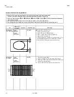
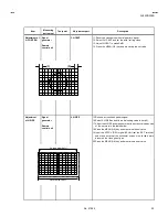
Page 34: ...ent Test point Adjustment part Description Set the ASPECT MODE to FULL Adjustment of V POSITION Signal generator Remote control unit 1 V SHIFT 1 Receive a circle pattern signal 2 Select 4 DEF from the SERVICE MENU 3 Select 1 V SHIFT with the FUNCTION key 4 Adjust V SHIFT to make A B 5 Check the adjustment condition in other aspect mode If it is a wrong condition re adjust in FULL mode with 1 V SHI...

Page 35: ...t of H SIZE Signal generator Remote control unit 4 H SIZE 15 Receive a crosshatch pattern signal 16 Select 4 H SIZE and set the initial setting value to zero 0 17 Adjust the H SIZE and make sure that the horizontal screen size of the picture is in the table bellow 18 Press the MENU OK key and memorize the set value 19 Input the NTSC VIDEO signal 60Hz from the EXT terminal and make sure that the ho...

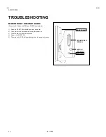
Page 36: ...rnatively 1 Press the RESET SW while the power is turned off 2 Then wait for two seconds after turning the power on 3 Tune the power off after two seconds 4 Release the RESET PW 5 The main unit of PDP will be activated when the power is tuned on RECEIVER INPUT TERMINAL AUDIO IN sub woofer RESET SW MONITOR UNIT ...

Reviews: