No. 51955
AV42PD20ES
14
LOWER BLOCK
REMOVING THE LOWER BLOCK
[NOTE]
The periphery of the receiver unit is a wooden cabinet. When the
receiver unit is removed, hold it up slightly with both hands and
put a mat or the like (cardboard, etc.) under the receiver unit s o
as to prevent scratching the cabinet during the removal work.
Then remove the rec eiver unit by withdrawing it toward you.
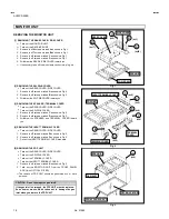
[1] REMOVING THE RECEIVER UNIT
1. Remove the
4
screws marked
A
as shown in Fig.3.
2. Slightly raise the both sides of the rec eiver unit by hand and
remove the receiver unit toward you.
*
Thus the c onnector should be securely inserted when the
receiver unit is installed again.
3. Unplug the connectors from the receiver unit.
4. Withdraw the receiver unit back ward.
[2] REMOVING THE CASE COVER OF THE RECEIVER UNIT
•
Take out the RECEIVER UNIT.
1. Remove the
10
screws marked
A
as shown in Fig.4.
2. Withdraw the case cover toward you from chassis cas e.
[3] REMOVING THE AV PLATE AND CHASSIS BEAM
•
Take out the RECEIVER UNIT.
•
Take out the CASE COVER.
1. Remove the
6
screws marked
B
as shown in Fig.4.
2. Unplug the connectors from the AV PLATE
3. Withdraw the AV PLATE toward you.
4. Remove the
2
screws marked
C
as shown in Fig.4.
5. Withdraw the chass is beam toward you from chassis cas e.
[4] REMOVING THE UNDER PANEL (L&R)
•
Take out the RECEIVER UNIT.
1. Remove the
2
screws marked
D
(L&R) as shown in Fig.5.
2. Remove the
4
screws marked
H
(L&R) as shown in Fig.5.
3. As shown Fig.5, remove the under panel (L&R) in the arrow
direction marked
I
.
[5] REMOVING THE FRONT CONTROL PWB
•
Take out the RECEIVER UNIT.
4. Remove the
3(2+1)
screws marked
A
as shown in Fig.5.
5. Remove the
6
screws marked
B
on the FRONT CONTROL
PWB as shown in Fig.5.
*
If nec essary, take off the wire clamp, connectors, etc.
[6] REMOVING THE SPEAKER NET / CENTER PANEL / FRONT
SW PWB / SW LEVER
1. Remove the
4
screws marked
C
(L&R side) as shown in
Fig.5.
2. Then withdraw the SPEAKER NET toward you.
3. Remove the
4
screws marked
E
as shown in Fig.5.
4. Then remove the CENTER PANEL / FRONT SW PWB & SW
LEVER as shown in Fig.5.
[7] REMOVING THE SPEAKER
•
Take out the SPEAKER NET.
1. Remove the
4
screws marked
F
as shown in Fig.5.
2. Follow the same steps when removing the other hand
speaker.
3. Remove the
4
screws marked
G
as shown in Fig.5.
CHECKING THE PW BOARD
1. To check the back side of the PW BOARD.
1) Pull out the chassis .
2) Erect the chas sis vertically so that you can easily check the
back side of the PW BOARD.
[CAUTION]
"
When erecting the PW BOARD, be careful so that there will be no
contacting with other PW BOARD.
"
Before turning ON power, mak e sure that the wire c onnector is
properly connec ted.0
"
When conducting a check with power supplied, be sure to c onfirm
that the EARTH WIRE is connected to the PW BOARD and
others PW BOARD.
WIRE CLAMPING AND CABLE TYING
1. Be sure to clamp the wire.
2. Never remove the c able tie used for tying the wires together.
Should it be inadvertently removed, be sure to tie the wires with a
new cable tie.


