

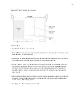


3. Connect the power cables to the power supplies.
identifies the cabling requirements.
Table 26: CTP Power Supply Cables and Wires Needed
To
From
Cable/Wire
Termination ground
PDU ground terminal
One 18-AWG ground wire
Appropriate leads on power source
No.1
PDU Power A –48 VDC and RTN leads
Two 18-AWG wire leads
Appropriate leads on power source
No.2
PDU Power B –48 VDC and RTN leads
Two 18-AWG wire leads
1.
Task 1: Turning Off All CTP Platform Power | 112
2.
Task 2: Connecting the Grounding Cable to the CTP Platform (CTP2056 Platform Only) | 112
3.
Task 3: Connecting the Power Cables to the CTP2000 Platform | 113
Task 1: Turning Off All CTP Platform Power
Push all device power switches to OFF to turn off the device.
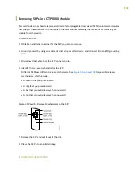
Task 2: Connecting the Grounding Cable to the CTP Platform (CTP2056 Platform Only)
The CTP2056 device has a grounding stud located in the rear of the chassis, near the power inputs.
To ground the power unit:
1. Locate the grounding stud.
2. Remove the nuts and locking washers from the grounding stud.
NOTE:
We recommend a minimum of 18-AWG ground wire with a ring-style terminal.
3. Place the grounding cable lead on the grounding stud, and tighten the nuts to secure the connection.
4. Connect the other end of the ground cable to the appropriate ground termination lead.
112
Summary of Contents for CTP2000 Series
Page 1: ...CTP2000 Series Circuit to Packet Platforms Hardware Guide Published 2020 08 31 ...
Page 8: ...1 PART Overview CTP2000 Series Platform Overview 2 CTP2000 Series Interface Modules 11 ...
Page 112: ...Installing SFPs in a CTP2000 Module 102 105 ...
Page 127: ...5 PART Configuration Accessing the CTP2000 Platform 121 ...
Page 144: ...7 PART Troubleshooting Troubleshooting Power Failures 138 Contacting Customer Support 140 ...


