Juniper BT8A78CH1 Hardware Overview And Installation Manual Download Page 82

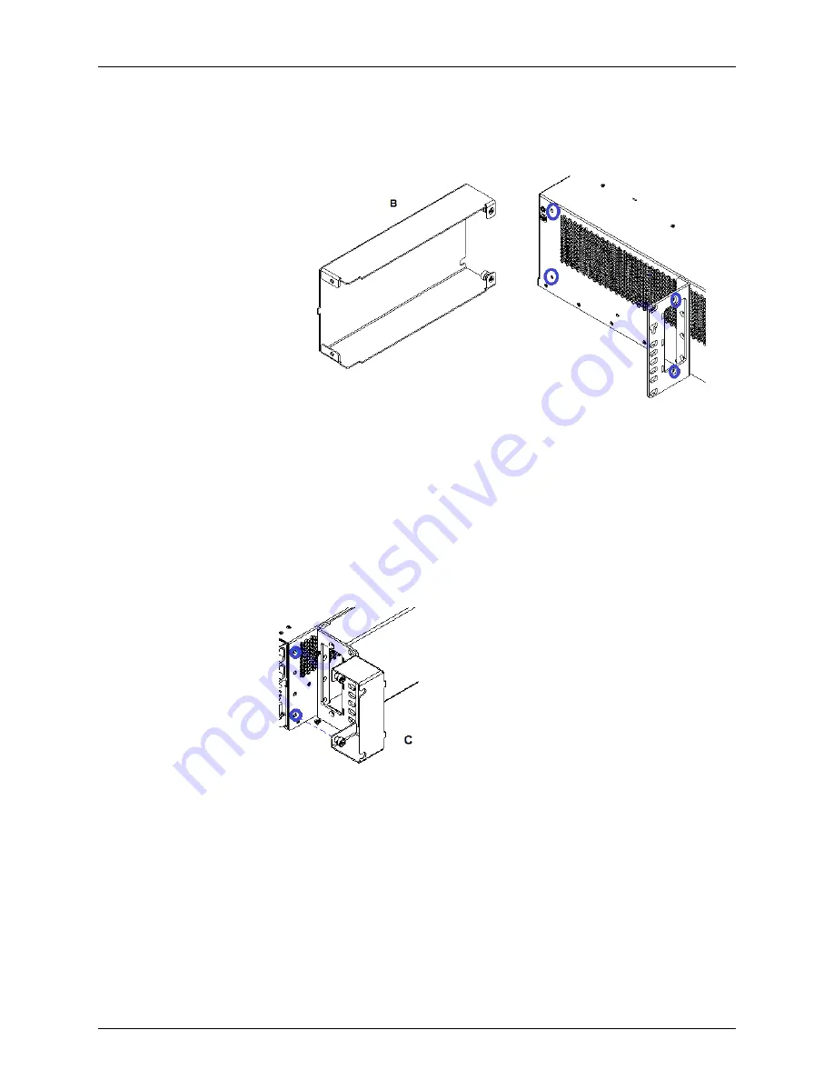
a. Place the air deflector behind the 23-inch mounting bracket.

b. Insert the metal tab into the slot of the 23-inch mounting bracket.

c. Align the bracket drill holes with the mounting bracket screw inserts. Fasten the

bracket to the mounting bracket using the two M3.5 screws.

d. Align the captive screws on the rear of the bracket to the chassis screw inserts.

Fasten the captive screws.

e. Ensure all surfaces are flush.

3.

Install the right front air intake.

a. Place the air intake in front of the 23-inch mounting bracket.

b. Insert the metal tab into the slot of the 23-inch mounting bracket.

c. Align the captive screws on the bracket to the chassis screw inserts. Fasten the

captive screws.

d. Ensure all surfaces are flush.

4.

Install the left front cover.

Copyright © 2019, Juniper Networks, Inc.

82

BTI7800 Series Hardware Overview and Installation Guide

Summary of Contents for BT8A78CH1

Page 1: ...BTI7800 Series Hardware Overview and Installation Guide Modified 2019 01 28 Copyright 2019 Juniper Networks Inc...

Page 2: ...opyright 2019 Juniper Networks Inc All rights reserved The information in this document is current as of the date on the title page YEAR 2000 NOTICE Juniper Networks hardware and software products are...

Page 3: ...ction 24 APR on 96 Channel Amplifier Modules 25 Safety Rating and Label 25 BTI7800 Series Laser Output Ports 26 Critical Site Warnings and Requirements 26 Critical Safety Warnings 28 NEBS Requirements...

Page 4: ...CAP 65 BTI7814 CAP 65 BTI7814 CAP1 Specifications 66 BTI7802 CAP 66 BTI7802 CAP2 Specifications 67 BTI7801 CAP 67 Chapter 3 Unpacking the BTI7800 Series Shipment 69 Unpacking the Equipment 69 Verify S...

Page 5: ...Removal Guidelines 108 Chassis Management Module CMM 110 CMM1 Specifications 111 CMM1 Latches 113 Installing a CMM 113 Removing a CMM 114 Universal Forwarding Module UFM 115 UFM Specifications 116 UFM...

Page 6: ...le Units FRUs 179 Replacing the BTI7814 DC PEM 180 Replacing the BTI7814 AC PEM 182 Replacing the Fuses on a BTI7814 AC PEM 185 Replacing the BTI7814 CAP 187 Replacing a BTI7814 FAN3 188 Replacing a B...

Page 7: ...223 Inspecting Fiber Optic Connectors 223 Cleaning Fiber Optic Connectors 224 Fiber Breakout 225 Fiber Breakout for UFM6 QSFP Ports 225 GigaLight SMF Elite MTP Angled LC UPC 1x8F to MTP MiniCassette...

Page 8: ...Copyright 2019 Juniper Networks Inc viii BTI7800 Series Hardware Overview and Installation Guide...

Page 9: ...g Module Location 58 Figure 15 2 Slot Chassis Cooling Module BT8A78FAN2 Right and Left Side Views 59 Figure 16 BTI7802 Cooling System 59 Figure 17 BTI7802 Cooling System with Rear Exhaust Adapter 60 F...

Page 10: ...139 Figure 43 Top Latch 2 WPS4 139 Figure 44 Bottom Latch WPS4 139 Figure 45 Front Panel 142 Figure 46 Block Diagram 143 Figure 47 23 inch Bracket Mounting Positions 147 Figure 48 21 inch Bracket Mou...

Page 11: ...Power Distribution 41 Table 18 BTI7814 14 Slot Chassis DC Power Entry Module BT8A78PEM3 DC Specifications 43 Table 19 BTI7814 AC Power Entry Module BT8A78ACM1 Specifications 46 Table 20 BTI7802 1 Slot...

Page 12: ...52 Service Module LED Behavior 151 Table 53 Port LEDs UFMs and BICs 152 Table 54 Port LEDs UFMs and Optical Modules 152 Chapter 6 BTI7800 Series Transceiver Specifications 153 Table 55 BTI7800 Series...

Page 13: ...Switch OPS 211 Table 80 Optical Protection Switch Kit Dual Switch Card BT7A39AS 212 Table 81 AC Power and Power Cables 212 Table 82 OPS Specifications 213 Table 83 OPS AC power unit BT7A39AE Specifica...

Page 14: ...Copyright 2019 Juniper Networks Inc xiv BTI7800 Series Hardware Overview and Installation Guide...

Page 15: ...s www juniper net documentation If the information in the latest release notes differs from the information in the documentation follow the product Release Notes Juniper Networks Books publishes books...

Page 16: ...the configure command user host configure Represents text that you type Bold text like this user host show chassis alarms No alarms currently active Represents output that appears on the terminal scr...

Page 17: ...sign community name members community ids Encloses a variable for which you can substitute one or more values square brackets edit routing options static route default nexthop address retain Identifi...

Page 18: ...ps www juniper net us en local pdf resource guides 7100059 en pdf Product warranties For product warranty information visit https www juniper net support warranty JTAC hours of operation The JTAC cent...

Page 19: ...s entitlementsearch juniper net entitlementsearch Creating a Service Request with JTAC You can create a service request with JTAC on the Web or by telephone Visit https myjuniper juniper net Call 1 88...

Page 20: ...Copyright 2019 Juniper Networks Inc xx BTI7800 Series Hardware Overview and Installation Guide...

Page 21: ...ice This precaution includes using optical loss test OLT set optical spectrum analyzer OSA and optical time domain reflectometer OTDR equipment Exclude any unauthorized personnel from the immediate la...

Page 22: ...sautomaticpowershutdown APSD andautomaticpowerreduction APR to shut off or reduce the output powers when a fiber is cut Table 3 Timing of APSD and APR Operations Output Level After Activation Activati...

Page 23: ...output WDM signal on the line port is automatically shut down or disabled from turn up if either of the following conditions occurs Cond 1 A Loss of Light fault is active against the input WDM and inp...

Page 24: ...laser when a fiber cut is detected WARNING APR is performed in software on the service module and is disabled whenever the service module undergoes a warm or cold reload In a cold reload the lasers ar...

Page 25: ...a safe level Client Out port APR is triggered when the optical back reflection OBR exceeds the threshold and the output power is larger than 5 dBm When APR is triggered the output of the laser on the...

Page 26: ...528 578 nm to 1566 928 nm BT8A78MD03 96 Channel Fixed Mux Demux C1 Out A L1 Out B L1 Out A C2 Out A L2 Out B L2 Out A C3 Out A L3 Out B L3 Out A C4 Out A L4 Out B L4 Out A C band 1500 to 1570 nm O ban...

Page 27: ...trical See the electrical requirements in BTI7802 Power on page 48 BTI7802 BT8A78CH2 I02 See the electrical requirements in BTI7801 Power on page 52 BTI7801 BT8A78CH1 Always use ESD grounding devices...

Page 28: ...00 Series chassis or other provisioned circuit packs when they are energized can cause serious injury or death NEBS Requirements The following table lists some important regulatory requirements for NE...

Page 29: ...les that transpond and muxpond traffic on 10 Gbps and 100 Gbps interfaces including 100 Gbps coherent DWDM Together with its ROADM capabilities the BTI7800 Series provides a complete end to end optica...

Page 30: ...in 19 inch 23 inch and ETSI 600 mm racks Table 7 BTI7814 Chassis Overview Access Component Front CMM Slots A and B to support up to two Chassis Management Modules System control Front Front panel disp...

Page 31: ...Figure 3 BTI7814 Chassis Front View Figure 4 BTI7814 Chassis Rear View with 14 Slot Chassis DC Power Entry Modules 31 Copyright 2019 Juniper Networks Inc Chapter 2 BTI7800 Series Chassis...

Page 32: ...e 9 BTI7814 Kits Component PEC Quantity Main Equipment Included Equipment common to all BTI7814 kits BT8A78CMM1 2 Chassis Management Module CMM1 BT8A78CAP1 1 14 Slot Chassis Alarm Panel CAP1 BT8A78FAN...

Page 33: ...N9 2 BTI7814 Booster Fan FAN9 BTI7814 Chassis Specifications Table 10 BTI7814 Chassis Specifications Specification Shell 24 5 in 621 mm 14 U Height 17 3 in 440 mm Width without mounting brackets 19 in...

Page 34: ...r the cooling module Two slots for service modules Two slots for redundant Chassis Management Modules Two slots for redundant PEM modules One slot for the Chassis Alarm Panel Figure 5 BTI7802 Chassis...

Page 35: ...FAN2 1 2 Slot Chassis Cooling Module FAN2 BT8A78FLR7 2 Line Card Filler Panels FLR7 BT8A78TOOLS 1 Chassis Common Tool Kit 2 slot Chassis DC KIT3 BT8A78CH2 KIT3 DC BT8A78PEM1 DC 2 1 Slot 2 SlotChassisD...

Page 36: ...slot Chassis DC KIT3 BT8A78CH2 KIT1 2 Slot Chassis DC KIT1 BT8A78CH2 KIT4 DC 2 slot Chassis DC KIT4 BT8A78CH2 KIT2 2 Slot Chassis DC KIT2 BT8A78CH2 KIT3 AC 2 slot Chassis AC KIT3 BT8A78CH2 KIT1 AC 2...

Page 37: ...nt connectivity The BTI7801 contains one service slot and one management slot and can be mounted onto 19 inch 23 inch and ETSI 600 mm 600 mm W x 800 mm D cabinets racks The service module and the cool...

Page 38: ...on Equipment Components Release Introduced PEC Component Release 2 1 BT8A78ESL1 Ethernet and Serial Link ESL module Release 2 1 BT8A78FAN5 1 Slot Chassis Front Cooling Module Release 1 3 BT8A78PEM1 DC...

Page 39: ...AC KIT1 BT8A78CH1 KIT1 AC BT8A78PEM1 AC 2 1 Slot 2 Slot Chassis AC Power Entry Module AC PEM BTI7801 Chassis Specifications Table 16 BTI7801 Chassis Specifications Specification Chassis 1U 1 7 in 44 m...

Page 40: ...to the Power Entry Modules The DC outputs of the Power Entry Modules are connected to the internal shelf input terminals A1 B1 A2 and B2 that in turn are connected to the power rails on the shelf The...

Page 41: ...use 3 Not applicable Future use 4 Service Modules Service module slots 9 and 10 5 Chassis Management Module CMM CMM slot B 6 Not applicable Future use Each channel has a fuse rating of 20 Amps BTI781...

Page 42: ...f input terminals The external A feed pair consists of two individual feeds A1 and A2 which connect to the external input terminals of PEM 1 and PEM 3 The DC outputs of PEM 1 and PEM 3 supply power to...

Page 43: ...Slot Chassis DC Power Entry Module BT8A78PEM3 DC Specifications Specification Item Physical Dimensions 159 mm 6 25 in Height 89 0 mm 3 50 in Width 157 0 mm 6 81 in Depth 0 7 kg 1 6 lb Weight 99 9 effi...

Page 44: ...use the chassis to operate unpredictably NOTE The REV LED indicates red to alert the installer that the chassis has been wired in reverse polarity The installer should switch the power OFF on the chas...

Page 45: ...ile the bottom two rectifiers are for the B feed pair For details on the power distribution plan see BTI7814 Power Distribution Plan on page 40 The external fuse breaker requirements for each feed is...

Page 46: ...If one 2900W 53 5V AC Rectifier Module is powered and the other 2900W 53 5V AC Rectifier Module in the same feed pair is seated but not powered the following occurs The unpowered 2900W 53 5V AC Recti...

Page 47: ...nd Power Supply Cords solid green protective earthing conductor acceptable Power Cable 12 AWG SJT Gauge IEC C21 Receptacle to chassis 110 V supply 3 IEC 5 20 240 V supply IEC 6 20 Plug to power source...

Page 48: ...EM while the redundant PEM continues to power the chassis For more information see BTI7802 Field Replaceable Units FRUs on page 193 BTI7802 Power Distribution Plan The BTI7802 supports redundant power...

Page 49: ...DC PEM BTI7802 DC PEM Specifications Table 20 BTI7802 1 Slot 2 Slot Chassis DC Power Entry Module BT8A78PEM1 DC Specifications Specification Item Physical Dimensions 85 mm 3 35 in Width 40 5 mm 1 59 i...

Page 50: ...N UL CSA ETSI Compliance BTI7802 AC PEM The BTI7802 chassis can be powered by up to two fan cooled 1 Slot 2 Slot Chassis AC Power Entry Modules BT8A78PEM1 AC Each AC PEM draws air from the front of th...

Page 51: ...C Power Entry Module BT8A78PEM1 AC Specifications Specification Item Physical Dimensions 85 0 millimeters 3 35 inches Width 40 5 millimeters 1 59 inches Height 305 millimeters 12 0 inches Depth 0 7 ki...

Page 52: ...nues to power the chassis For more information see BTI7801 Field Replaceable Units FRUs on page 199 BTI7801 Power Distribution Plan The BTI7801 supports redundant power feeds A and B that allow the ch...

Page 53: ...95 BT8A78UFM6 I02 UniversalForwardingModulewithIntegrated 400G Coherent MSA XCVR UFM6 75 68 BT8A78AMP1 96 Channel Amplifier AMP1 0 0 BT8A78MD03 96 Channel Fixed Mux Demux FMD96 24 22 BT8A78WPS4 Wavele...

Page 54: ...AC PEM 0 25 0 25 BT8A78ESL1 Ethernet and Serial Link ESL Pluggable Transceivers 1 0 8 BP3AD6SS SFP 850nm 200m Dual Rate 10 3 and 10 5Gbps 1 0 8 BP3AM6MS SFP 1310nm 10km Multi Rate 9 9 to 11 1Gbps 1 5...

Page 55: ...ng Modules FAN3 to supply front to back air flow through the chassis When one or more UFM6 modules are installed in the chassis two BTI7814 Booster Fan modules are required to provide additional cooli...

Page 56: ...CMM is not present The chassis is equipped with louver panels on the back exhaust of each cooling module to eliminate recirculating air when a cooling module fails NOTE The front and rear of the chas...

Page 57: ...ve CMM NOTE FAN9 modules can be managed by the CMM only if the system is running Release 4 1 or later software and firmware The FAN9 modules operate simultaneously at 19 percent of their maximum fan s...

Page 58: ...tworks Support to confirm the power consumption values 160 CFM Air Flow Active Green Fail Red LEDs BTI7802 Cooling System The BTI7802 chassis is shipped with the cooling module installed The cooling m...

Page 59: ...ule BT8A78FAN2 to create a side to side right to left air flow The air intake and exhaust are located at the sides of the chassis Figure 16 BTI7802 Cooling System An optional BTI7802 Chassis Rear Exha...

Page 60: ...Weight Typical 150W Maximum 180W Power Consumption 40 C ambient NOTE Before using for planning or implementation purposes contact Juniper Networks Support to confirm the power consumption values Maxi...

Page 61: ...ds the main chassis air exhaust at the rear Openings in the ESL slot allow some air to flow across the CMM and out the secondary air exhaust above the CMM If AC PEMs are installed the internal AC PEM...

Page 62: ...ating BTI7801 FAN5 Specifications Table 26 1 Slot Chassis Front Cooling Module BT8A78FAN5 Specifications Specification Item Physical Dimensions 71 mm 2 8 in Width 40 mm 1 6 in Height 295 mm 11 6 in De...

Page 63: ...CMM port the corresponding Link LED on the FAN5 module might light up even if no cable is connected to the FAN5 module Port LEDs BTI7801 FAN5 Management Ports and the ESL Module The FAN5 module can pr...

Page 64: ...78ESL1 Specifications Specification Item Physical Dimensions 44 mm 1 7 in Width 40 mm 1 6 in Height 295 mm 11 6 in Depth excluding handle 0 45 kg 1 lb Weight Typical 0 25 W Maximum 0 25 W Power Consum...

Page 65: ...e Port LEDs Chassis Alarm Panel CAP BTI7814 CAP on page 65 BTI7802 CAP on page 66 BTI7801 CAP on page 67 BTI7814 CAP The BTI7814 Chassis Alarm Panel CAP provides a set of relay contacts to signal alar...

Page 66: ...the power consumption values Critical Red LEDs Minor Amber Major Red OOS Out of service Red Power Green BTI7802 CAP The BTI7802 chassis is shipped with the Chassis Alarm Panel CAP module installed BT...

Page 67: ...4 W Power Consumption 40 C ambient NOTE Before using for planning or implementation purposes contact Juniper Networks Support to confirm the power consumption values Critical Red LEDs Minor Amber Maj...

Page 68: ...Copyright 2019 Juniper Networks Inc 68 BTI7800 Series Hardware Overview and Installation Guide...

Page 69: ...pment Leave equipment packed until it is needed for immediate installation After unpacking the equipment save and store the packaging material in case the equipment must be returned Inspect all sides...

Page 70: ...is Kits on page 32 BTI7802 Chassis Kits on page 35 or BTI7801 Chassis Kits on page 38 Lifting and Moving the BTI7814 Chassis This section describes how to use the optional 14 Slot Chassis Shelf Instal...

Page 71: ...hese modules Always use best practices to lift and move the chassis We recommend the following A minimum of two people Four people to provide proper balance and safety two at the front and two at the...

Page 72: ...the sides of the chassis At least one person should be positioned on each side of the chassis to grab a handle For proper balance an additional person should be positioned in front of the chassis and...

Page 73: ...NOTE For detailed rack mounting procedures refer to Rack Mounting the BTI7814 Chassis on page 84 73 Copyright 2019 Juniper Networks Inc Chapter 3 Unpacking the BTI7800 Series Shipment...

Page 74: ...Copyright 2019 Juniper Networks Inc 74 BTI7800 Series Hardware Overview and Installation Guide...

Page 75: ...NOTE Restricted Access refers to an inaccessible location that is normally inaccessible by the general public by means of any administrative or engineering control measure but is accessible to authori...

Page 76: ...llation kits that include the hardware needed to mount power and ground the chassis The BTI7800 Series Chassis Common Tool Kit BT8A78TOOLS includes BIC extractor tools an adjustable wrist strap and th...

Page 77: ...ire 5 8 Stud pitch 1 4 Stud diameter Installation hardware plastic shipping bag 1 Packing bag for installation kit The following kits and cables are optional and must be ordered separately Table 33 Mi...

Page 78: ...fastening mounting brackets onto a BTI7814 chassis Grounded antistatic mat to place modules ESD grounding strap to prevent electrostatic discharge damage Wire stripping and crimping tool Multimeter T...

Page 79: ...y qualified personnel Make sure you are familiar with the site and safety guidelines Use an ESD wrist strap whenever you handle equipment Install the Rear Exhaust Adapter before mounting the chassis o...

Page 80: ...eflector with rear exhaust B 2 captive screws fasten to chassis Right front air intake C 2 captive screws fasten to chassis Left front cover D Tools required Number 1 Phillips screwdriver the shaft of...

Page 81: ...t drill holes with the mounting bracket screw inserts Fasten the bracket to the mounting bracket using the two M3 5 screws d Align the captive screws on the rear of the bracket to the chassis screw in...

Page 82: ...racket to the chassis screw inserts Fasten the captive screws e Ensure all surfaces are flush 3 Install the right front air intake a Place the air intake in front of the 23 inch mounting bracket b Ins...

Page 83: ...of the 23 inch mounting bracket c Align the captive screws on the bracket to the chassis screw inserts Fasten the captive screws d Ensure all surfaces are flush You have successfully completed this p...

Page 84: ...page 84 Rack Mounting the BTI7802 Chassis on page 86 Rack Mounting the BTI7801 Chassis on page 87 Rack Mounting the BTI7814 Chassis Use this procedure to mount the BTI7814 onto a rack Table 34 Rack M...

Page 85: ...k each positioned at a corner of the chassis 3 With the chassis front facing grasp the chassis from the bottom with all personnel positioning their hands on the chassis in the positions stated in Step...

Page 86: ...g brackets are packaged as a separate item and are shipped with the chassis Before you begin this procedure you should remove unnecessary mounting brackets by unfastening and removing the screws that...

Page 87: ...completed this procedure Rack Mounting the BTI7801 Chassis Table 36 Rack Mounting Considerations Support Measurement ANSI 19 in ETSI 600 mm ANSI 23 in Rack size ANSI 19 in ETSI 600 mm x 800 mm NOTE En...

Page 88: ...post holeone screw in the top bracket hole on each side and one screw in the bottom bracket hole on each side When all the screws are in place tighten the screws into the rack post 6 If you are mounti...

Page 89: ...You must complete this procedure before connecting power and powering on the chassis The chassis voltage is considered hazardous NOTE NEBS Compliance Statements for GR 1089 Only copper cables are to...

Page 90: ...e other end of the grounding wire with a dual stud lug and connect it to the frame with the two screws and four lock washers one on each side of each lug hole supplied in the installation kit 6 Check...

Page 91: ...ble from the rear It is identified by a grounding label 1 Use a wire stripper tool to strip the end of the ground wire to the correct length 5 0 mm 0 2 in for crimping the supplied ring lugs 2 Insert...

Page 92: ...I7801 uses DC I grounding configuration with the return ground isolated from the frame ground WARNING You must complete this procedure before connecting power and powering on the chassis The chassis v...

Page 93: ...ct length 5 0 mm 0 2 in for crimping the supplied ring lugs 2 Insert the stripped end of the grounding wire into the open end of the lug 3 Use a ring lug crimping tool do not use pliers to secure the...

Page 94: ...on page 94 Powering the BTI7802 Chassis on page 100 Powering the BTI7801 Chassis on page 105 Powering the BTI7814 Chassis Connecting the DC Power Feeds to a BTI7814 DC PEM on page 94 Connecting the AC...

Page 95: ...s Hardware Overview and Installation Guide WARNING Before you proceed Do not work alone The chassis must be grounded to the frame in which it is mounted The power source to which you are connecting th...

Page 96: ...pare the power cables as needed for attachment to the chassis a Use a wire stripper tool to strip one end of the power cable to the correct length 5 0 mm 0 2 inch for crimping on the supplied dual stu...

Page 97: ...om the Feed to the Return Positive Return Within less than 2V of the frame or chassis ground You have successfully completed this procedure Connecting the AC Power Feeds to a BTI7814 AC PEM If you ord...

Page 98: ...pecified in BTI7814 AC PEM Specifications on page 46 Procedure 1 Verify that there is no power going to the chassis 2 Verify that the chassis is properly grounded For information on frame grounding th...

Page 99: ...99 Copyright 2019 Juniper Networks Inc Chapter 4 Installing the BTI7800 Series Chassis...

Page 100: ...ch on one rectifier at a time The AC PEM LED starts to light up The AC OK light turns solid green when the module is ready Wait for the AC OK light before proceeding to power the next rectifier You ha...

Page 101: ...site and safety guidelines described in the BTI7800 Series Hardware Overview and Installation Guide WARNING Before you proceed Do not work alone The chassis must be grounded to the frame in which it i...

Page 102: ...ector and cable and prepare it as needed for connection to the DC power distribution unit in your plant 4 Install the DC PEM Loosen the latch thumbscrew and pull the latch to the open position 5 Posit...

Page 103: ...completed this procedure Installing and Cabling the BTI7802 AC PEM If you order the BTI7802 chassis with the AC option the chassis is shipped with the 1 Slot 2 Slot Chassis AC Power Entry Modules AC...

Page 104: ...2 Verify that the chassis is properly grounded For information on frame grounding the chassis reference Frame Grounding a BTI7802 Chassis on page 90 3 Install the AC PEM Loosen the latch thumbscrew a...

Page 105: ...802 See Installing and Cabling the BTI7802 AC PEM on page 103 for installation and cabling instructions Connecting the ESD Wrist Strap Cable Plug in the supplied ESD wrist strap cable to the ESD jack...

Page 106: ...en the lower Chassis Management Module slot and the Power Entry Module BTI7801 ESD Jack Location There is one ESD jack on the BTI7801 chassis At the front of the chassis top right corner above the cab...

Page 107: ...er traffic and include service modules BTI Interface Cards and passive rack mounted modules Table 38 BTI7800 Series Management and Traffic Modules Introduced PEC Description Module Management modules...

Page 108: ...rts 1 to 10 support QSFP transceivers and client ports 1 2 6 7 support both QSFP and QSFP28 transceivers Module Installation and Removal Guidelines All management and traffic modules are hot swappable...

Page 109: ...installed the faceplate will be in line with other installed modules and the latches will be secured correctly The thumbscrews used to secure the module can be operated by hand or with a screwdriver...

Page 110: ...as power cycle or reset of managed entities Provides low level hardware management services to manage the power cooling and interconnect resources of a chassis Provides non volatile storage of configu...

Page 111: ...View CMM1 Specifications Table 40 Chassis Management Module 1 BT8A78CMM1 Specifications Specification Item Physical Dimensions 212 9 mm 8 38 in Width 314 4 mm 1 12 in Height 30 5 mm 12 38 in Depth 1 3...

Page 112: ...p bit RS232 RJ45 Craft Serial 10 100 1000 Mbps IEEE 802 3 Ethernet RJ45 EXP 1 to EXP 3 10 100 1000 Mbps IEEE 802 3 Ethernet RJ45 Management Ethernet 10 100 1000 Mbps IEEE 802 3 Ethernet RJ45 Craft Eth...

Page 113: ...place for future use 2 Remove the module from its antistatic bag holding it by its edges and faceplate to prevent damage to the module circuitry Visually inspect the module including the pins and conn...

Page 114: ...ips screwdriver Antistatic bag NOTE Be familiar with the site safety and installation guidelines described in Module Installation and Removal Guidelines on page 108 1 Disconnect the cables from the mo...

Page 115: ...UFM4 BT8A78UFM4 Supports One integrated 400G Coherent MSA XCVR with two 200 Gbps ports QSFP QSFP28 client ports Ten QSFP ports 40x10 Gbps when deployed with ten GigaLight SMF Elite MTP Angled LC UPC 1...

Page 116: ...niversal Forwarding Module BT8A78UFM3 Typical 140 W Maximum 154 W Universal Forwarding Module with Integrated 100G Coherent MSA XCVR BT8A78UFM4 Typical With 10 x QSFP transceivers installed 305 W With...

Page 117: ...endable handle that provides leverage when you open or close the latch Figure 34 Bottom Latch UFMs Installing a UFM Use this procedure to install a Universal Forwarding Module UFM Prerequisites If you...

Page 118: ...rom the slot into which you are installing the module and store it in a safe place for future use 2 Remove the module from its antistatic bag holding it by its edges and faceplate to prevent damage to...

Page 119: ...d When the module is administratively disabled the hot swap LED shows a solid blue For information on how to disable the UFM see the BTI7800 Software Configuration Guide This procedure covers all UFM...

Page 120: ...FM4 with a UFM3 Prerequisites The UFMs must be similarly equipped See the BTI7800 Series Software Configuration Guide for the qualifying criteria This procedure describes a very specific type of UFM r...

Page 121: ...stall a 1x CFP BIC into BIC slot 1 and to reinstall the BIC that you removed in 2 into BIC slot 2 of the UFM 7 Install a 100G Coherent CFP into the 1x CFP BIC 8 Reconnect all fibers You have successfu...

Page 122: ...ent combinations of 10 Gbps and 100 Gbps interfaces There is no restriction on which BIC or which pairing of BICs can be installed in a UFM 12x SFP BIC on page 122 1x CFP BIC on page 124 BIC Handles a...

Page 123: ...eight Typical 38 W Maximum 43 W Power Consumption 40 C ambient NOTE Before using for planning or implementation purposes contact Juniper Networks Support to confirm the power consumption values See BI...

Page 124: ...975 1 SFP 12 Connectors Ports 1x CFP BIC The 1x CFP BTI Interface Card 1x CFP BIC contains one CFP transceiver Figure 36 1x CFP BTI Interface Card Table 45 1x CFP BIC BT8A78CFP1G Specifications Specif...

Page 125: ...he bottom The bottom latch must be fully closed for proper module operation Installing a BIC Use this procedure to install a BTI Interface Card BIC into a UFM Prerequisites If you have pre provisioned...

Page 126: ...pen position See BIC Handles and Latches on page 125 b Position the module BTI7814 Position the module vertically so that the faceplate is toward you and the latch is at the bottom BTI7801 BTI7802 Pos...

Page 127: ...Removal Guidelines on page 108 1 Move cables aside as needed to get clear access to the module 2 Disconnect the fibers from the BIC NOTE Ensurethatopticalcablesareprotectedwithprotectivecapswhile disc...

Page 128: ...dure to replace a BIC If you want to replace both BICs in a UFM you must replace one BIC at a time 1 Follow the procedure in Removing a BIC on page 126 to remove a BIC Remove only one BIC from the UFM...

Page 129: ...s blocking access 2 To install the filler panel a Insert the filler panel by engaging the bottom of the panel with the bottom of the slot The filler panel should be at an angle for example b Push the...

Page 130: ...Amplifier AMP1 The 96 Channel Amplifier module integrates two erbium doped optical amplifiers to provide bi directional amplification of DWDM optical signals in a point to point configuration The amp...

Page 131: ...AMP1 Specifications Specification Item Physical Dimensions 30 5 mm 1 20 in Width 350 8 mm 13 81 in Height 325 0 mm 12 80 in Depth 1 9 kg 4 2 lb Weight Typical 68W Maximum 75W Power Consumption 40 C am...

Page 132: ...OSC Wavelength 10 709 Gbps Supported Bit Rates 27 952 Gbps 111 809 Gbps 120 579 Gbps Class 1 Hazard 1M Optical Safety APSD Line port Optical Safety Protection Mechanisms APR DCM and C1 ports Span Los...

Page 133: ...If the module is not administratively enabled the module will not be acknowledged by the CMM For information on how to enable the module see the BTI7800 Software Configuration Guide If you have not p...

Page 134: ...es and carefully slide the module until it contacts the backplane e Press firmly on a part of the faceplate away from the latches The latches close by themselves as the module is seated Take care not...

Page 135: ...ueeze the spring loaded locking mechanism to disengage the latch from the module faceplate and pull the latches to the open and unlocked position to unseat the module See AMP1 Latches on page 133 6 Ge...

Page 136: ...1 C2A L2B L2A Wavelength protection group 2 C3A L3B L3A Wavelength protection group 3 C4A L4B L4A Wavelength protection group 4 WPS4 Specifications on page 137 WPS4 Latches on page 138 Installing a W...

Page 137: ...Wavelength Protection Groups C band 1500 to 1570 nm O band 1260 to 1350 nm L band 1560 to 1620 nm Operating Wavelength Range Automatic based on received power levels configurable threshold and manual...

Page 138: ...0 Monitor Range LnA_In dBm 18 0 40 0 Monitor Range LnB_In dB 1 3 1 3 Monitor Accuracy dB 45 0 Directivity LnA_IN to LnB_IN dB 45 0 Directivity LnA_OUT to LnB_OUT dB 50 0 Switch Isolation dB 0 2 Polar...

Page 139: ...S4 Installing a WPS4 Use this procedure to install a WPS4 Prerequisites If you have pre provisioned the module ensure the module is administratively enabled If the module is not administratively enabl...

Page 140: ...future use 2 Remove the module from its antistatic bag holding it by its edges and faceplate to prevent damage to the module circuitry Visually inspect the module including the pins and connectors th...

Page 141: ...ation guidelines described in Module Installation and Removal Guidelines on page 108 NOTE The wavelength ports do not support the ability to shut down the laser When the ports are optically connected...

Page 142: ...onal client ports with each client port carrying a different fixed wavelength See DWDM 50 GHz Wavelength Plan on page 219 for the wavelength to client port mapping See Figure 45 on page 142 Figure 45...

Page 143: ...96 does not process the OSC signal from the attached ROADM module Instead the FMD96 demultiplexes the OSC signal from the composite signal on the L1 In port and multiplexes it back into the composite...

Page 144: ...al 1566 72 nm 1528 77 nm Central Wavelengths C band 96 channels Number of Channels 50 GHz spacing 6 5 dB 4 0 dB Insertion Loss client in to line out 6 5 dB 4 0 dB Insertion Loss line in to client out...

Page 145: ...ot NEBS 3 certified The FMD96 is shipped as a complete unit with hinged cover and latch fiber support and 21 23 inch mounting bracket attached An installation kit with a 19 inch mounting bracket and i...

Page 146: ...ng position that ensures the FMD96 is flush with adjacent equipment The FMD96 is shipped with the mounting brackets installed in the 23 inch orientation and mounted in the mid position Copyright 2019...

Page 147: ...ed flush with adjacent equipment If required remove the mounting brackets and attach the brackets to the new mounting positions b To install the 21 inch brackets Figure 48 on page 147 Figure 48 21 inc...

Page 148: ...g position 2 Mounting position 2 Mount the module on the frame or the rack a With one person at each side of the module lift the module into position in the equipment frame b Align the mounting holes...

Page 149: ...er between the lug and the frame and between the lug and the screw head 4 Open the cover and connect fibers The fibers should be routed between the front panel and the front cover to allow for the cov...

Page 150: ...front cover and disconnect the fibers CAUTION When working with the FMD96 follow the safety procedures associated with equipment containing Laser Safety Hazard Level 1M CAUTION When the ports are opti...

Page 151: ...The CMM has identified and acknowledged the module The CMM can only acknowledge the module if the module is administratively up A newly inserted module is administratively up if either of the followin...

Page 152: ...m the chassis H S BLUE The administrative status of the module is down or the actual module does not match the provisioned module The module can be removed from the chassis in this state ON This is a...

Page 153: ...SFP BIC in UFM3 and UFM4 BP3AD6SS 10 3 and 10 5 Gbps Multimode SFP 850nm 200m Dual Rate 10 3 and 10 5Gbps Release 1 1 12x SFP BIC in UFM3 and UFM4 BP3AM6MS 9 9 to 11 1 Gbps Single mode SFP 1310nm 10k...

Page 154: ...GE AOC Release 4 3 UFM6 QSFP 100GBASE SR4 740 058734 100 Gbps Multimode QSFP28 100GE SR4 Release 4 3 UFM6 QSFP 100G LR4 D 740 073859 100 Gbps Single mode QSFP28 100GE Ethernet OTN LR4 Release 4 1 UFM6...

Page 155: ...warding Module with Integrated 400G Coherent MSA XCVR BT8A78UFM6 I02 2 x 200 Gbps Single mode 400G Coherent MSA XCVR BTI7800 SFP Transceiver Optical Specifications NOTE Contact Juniper Networks Suppor...

Page 156: ...m 1 W Power Consumption 40 ambient IEEE 802 3 SFP MSA Compliance Table 57 SFP 1310nm 10km Multi Rate 9 9 to 11 1Gbps BP3AM6MS Units Maximum Typical Minimum Parameter Gbps 11 0957 9 953 Bit Rate Transm...

Page 157: ...GR 253 ITU T G 709 SFP MSA Compliance Table 58 SFP DWDM Fixed 80km Multi Rate 9 9 to 11 1Gbps BP3AM6DL xx Xx 01 40 Units Maximum Typical Minimum Parameter Gbps 11 0957 9 953 Bit Rate Transmitter THz...

Page 158: ...Table 59 Receiver Transmission Optical Performance Specifications BP3AM6DL xx Xx 01 40 BER Receiver Sensitivity Min to Max OSNR dB Dispersion ps nm Bit Rate Gbps 1e 12 24 to 7 30 400 9 95 10 3 18 to 7...

Page 159: ...s nm Bit Rate Gbps 1e 4 24 to 7 30 400 10 7 FEC G 709 18 to 7 19 23 to 7 30 0 18 to 7 19 22 to 7 30 1200 18 to 7 28 24 to 7 30 1600 18 to 7 19 1e 3 25 to 7 30 400 10 7 EFEC 18 to 7 17 27 to 7 30 0 18...

Page 160: ...00 18 to 7 19 1e 3 25 to 7 30 400 11 1 EFEC 18 to 7 17 27 to 7 30 400 to 0 18 to 7 16 25 to 7 30 1200 18 to 7 16 25 to 7 30 1600 18 to 7 17 Table 60 SFP DWDM Tunable 80km Multi Rate 9 9 to 11 1Gbps BP...

Page 161: ...r Latch type Typical 1 7 W Maximum 2 W Power Consumption 40 ambient IEEE 802 3 Telcordia GR 253 ITU T G 709 SFP MSA Compliance Table 61 Receiver Transmission Optical Performance Specifications BP3AM6T...

Page 162: ...fore using for planning or implementation purposes Table 62 QSFP 4x10GBASE LR QSFPP 4X10GE LR 740 054050 Units Maximum Typical Minimum Parameter Gbps 10 3125 100 ppm Signaling speed per lane 4 Number...

Page 163: ...40 058730 Units Maximum Typical Minimum Parameter Gbps 10 3125 10GBASE Signaling speed per lane Gbps 9 95428 OC192 STM64 Gbps 10 709 OTU2 Gbps 11 0957 OTU2e Gbps 8 5 100 ppm 8GFC Gbps 10 51875 100 ppm...

Page 164: ...on ratio dB 6 OC192 STM64 dB 6 OTU2 dB 6 OTU2e dB 3 5 8GFC dB 3 5 10GFC dB 12 Optical return loss tolerance Receiver dBm 0 5 14 4 Average receive power per lane dBm 10 3 Stressed receiver sensitivity...

Page 165: ...Bm 1 3 7 3 10GBASE 40GBASE Average launch power per lane dBm 1 3 8 2 8GFC dBm 1 3 7 3 10GFC dB 3 Extinction ratio dB 12 Optical return loss tolerance Receiver dBm 1 0 9 9 10GBASE 40GBASE Average recei...

Page 166: ...00 ppm Signaling speed per lane 4 Number of lanes nm 860 840 Lane center wavelength Transmitter dBm 2 4 7 6 Average launch power per lane dB 3 Extinction ratio dB 12 Optical return loss tolerance Rece...

Page 167: ...1317 5 1337 5 1264 5 1284 5 1304 5 1324 5 Lane center wavelength Transmitter dBm 2 3 7 Average launch power per lane dB 3 5 Extinction ratio dB 20 Optical return loss tolerance Receiver dBm 2 3 13 7...

Page 168: ...1294 53 1296 59 1299 02 1301 09 1303 54 1305 63 1308 09 1310 19 Lane center wavelengths range Transmitter dBm 4 5 4 3 Average launch power per lane dB 4 Extinction ratio dB 20 Optical return loss tole...

Page 169: ...53 1296 59 1299 02 1301 09 1303 54 1305 63 1308 09 1310 19 Lane center wavelengths range Transmitter dBm 4 5 4 3 100GBASE Average launch power per lane dBm 4 0 6 OTN dB 4 100GBASE Extinction ratio dB...

Page 170: ...meter Gbps 25 78125 100 ppm Signaling speed per lane 4 Number of lanes nm 860 840 Lane center wavelengths range Transmitter dBm 2 4 8 4 Average launch power per lane dB 2 Extinction ratio dB 12 Optica...

Page 171: ...OC 10M 740 061411 10 m JNP 100G AOC 15M 740 068217 15 m JNP 100G AOC 20M 740 064981 20 m JNP 100G AOC 30M 740 064980 30 m Reach Not applicable Connector Latch type Maximum 3 5 W Power consumption IEEE...

Page 172: ...receiver sensitivity per lane dBm 3 4 Rx overload dB 3 5 Optical path penalty Other Typical 10W Maximum 12W Power Consumption 40 ambient IEEE 802 3 CFP MSA Compliance Table 72 CFP 100GBASE LR4 10km BP...

Page 173: ...Typical 20W Maximum 24W Power Consumption 40 ambient IEEE 802 3 Telcordia GR 253 ITU T G 709 CFP MSA Compliance Table 73 100G Coherent CFP M05 CFP 100GBASE CHRT Units Maximum Typical Mininum Parameter...

Page 174: ...umption 40 ambient IEEE 802 3 Telcordia GR 253 ITU T G 709 CFP MSA Compliance Table 74 100G Coherent CFP BP3AMCTL Units Maximum Typical Minimum Parameter Transmitter THz 196 10 191 35 Transmitter freq...

Page 175: ...CVR on UFM4 Units Maximum Typical Minimum Parameter Transmitter THz 196 10 191 35 Transmitter frequency range GHz 1 8 1 8 Laser frequency stability dBm 1 5 Output power tuning range dB 40 Transmitter...

Page 176: ...erent MSA XCVR 2 X 200 Gbps on UFM6 Units Maximum Typical Minimum Parameter Transmitter THz 196 10 191 35 Transmitter frequency range GHz 1 8 1 8 Laser frequency stability dBm 2 5 10 Output power tuni...

Page 177: ...vertically Placement within the UFM The UFM with the 100G Coherent CFP must be installed to the immediate right of a fully occupied slot or in slot 1 leftmost slot of the chassis A fully occupied slo...

Page 178: ...Copyright 2019 Juniper Networks Inc 178 BTI7800 Series Hardware Overview and Installation Guide...

Page 179: ...possible hazardous condition Safety Warnings This equipment is intended to be installed and serviced by qualified personnel Be familiar with the safety guidelines described in the BTI7800 Series Hardw...

Page 180: ...I7814 Booster Fan on page 189 Performing a First Time Installation of the BTI7814 Booster Fans on page 190 Replacing a BTI7814 Air Filter on page 191 Replacing the BTI7814 DC PEM Use this procedure to...

Page 181: ...avoid damage to DC PEM components Once the module is removed place it in an antistatic bag or on a grounded antistatic mat 6 Install the replacement DC PEM Carefully slide the module along the slot gu...

Page 182: ...e removed PEM into another slot or chassis Tools Required Number 2 Phillips screwdriver Multimeter 1 Identify the faulty PEM The faulty PEM has the red or amber LED illuminated 2 Turn off power and un...

Page 183: ...mating PEM connector on the backplane d Still grasping the latch pivot the AC PEM module towards you and remove it from the housing e Place the module into an anti static bag or on a ground mat NOTE...

Page 184: ...ch is not engaged with the housing the latch will close but the module will not seat 6 Reinstall the housing cover a Orient the cover by aligning the three slots in the cover with the three flanges on...

Page 185: ...WARNING Ensurethatyouarefamiliarwiththesafetyandelectricalwarnings described in BTI7814 Field Replaceable Units FRUs on page 179 NOTE The cause of the blown fuse must be understood and the problem rec...

Page 186: ...f the fuse array to which you need to gain access 5 Using needle nose pliers extract the fuse you want to replace and discard appropriately 6 Using needle nose pliers insert the replacement fuse of th...

Page 187: ...hey are disengaged from their threaded holes b Use the two thumbscrews on each side as handles and pull the cover outwards towards your body to disengage from the top edge c Lift the cover out from th...

Page 188: ...opped before proceeding to the next step b Hold the cooling module handle and slowly slide the module out of the chassis 3 Place the cooling module in an antistatic bag or a grounded antistatic mat 4...

Page 189: ...the module to the chassis and grasp the module by its handle b Wait for the module s fans to stop c Carefully slide the module out of the chassis and place it either in an antistatic bag or on a grou...

Page 190: ...on page 179 Tools Required Number 2 Phillips screwdriver 1 At the rear of the chassis use the screwdriver to unfasten the four screws that secure the ventilation cover and then pull the cover away fr...

Page 191: ...e Replacing a BTI7814 Air Filter Use this procedure to replace an air filter on the BTI7814 chassis The air filter is hot swappable and can be replaced while the system is powered on and operational T...

Page 192: ...the holding flange lift the filter element away from the bottom rail guide 6 Install the new air filter element into the bracket a Insert the new air filter element into the bottom rail guide b Using...

Page 193: ...res ESD can occur when a module is improperly handled To prevent ESD damage to a module follow these guidelines Always wear an ESD grounding device such as an ESD wrist strap when handling a module Do...

Page 194: ...atch thumbscrew Pull the latch into the open position b Slowly pull out the module Once the module is removed place it in an antistatic bag or on a grounded antistatic mat NOTE If you plan on reusing...

Page 195: ...other obstructions 2 Loosen the thumbscrew at the top of the module 3 Carefully grip the handle Gently pull the module out of the chassis 4 Place the module in an antistatic bag or on a grounded anti...

Page 196: ...86 o F working ambient Tools Required Number 2 Phillips screwdriver NOTE The BT8A78CH2 I02 chassis supports the BT8A78FAN2 cooling moduleonly AnEquipmentMismatch eqptMism alarmisraisedifadifferent coo...

Page 197: ...filter should be replaced every six months in a clean environment If the dust level in your plant is high replace the filter every three months Usually the air filters in chassis installed lower in a...

Page 198: ...e screw is captive in the cover Use the finger and thumb inserts on the filter cover as an aid to detach the cover 2 Remove the air filter from the channel and discard it 3 Ensure the channel is free...

Page 199: ...installed and serviced by qualified personnel Be familiar with the safety guidelines described in the BTI7800 Series Hardware Overview and Installation Guide Ensure the chassis is installed properly...

Page 200: ...uctions Replacing the BTI7801 FAN5 Use this procedure to replace a 1 Slot Chassis Front Cooling Module on the BTI7801 chassis The cooling module is hot swappable and can be replaced while the system i...

Page 201: ...e until it is connected to the backplane Once the module is in its place the Active LED turns solid green 6 Tighten the thumbscrew You have successfully completed this procedure Replacing the BTI7801...

Page 202: ...lowly slide the ESL module out 4 Place the ESL module in an antistatic bag or on a grounded antistatic mat 5 Align the replacement ESL module with the slot guides 6 Gently push the module until it is...

Page 203: ...g and supports up to three rectifiers The shelf includes three IEC 60320 C19 C20 AC plugs with a 20 Amp rating and each rectifier is powered by a single plug The fourth slot contains a management modu...

Page 204: ...U Power Shelf 3 C19 AC plug 14 AWG power cords 2 brackets 4 screws Mounting brackets and screws for 23 rack 1 Advanced Controller Card Extended ACC 1 PEM cable jumper and cable kit 1 single hole 1 dou...

Page 205: ...k One above the BTI7814 One below the BTI7814 Shelf placement in rack Installing the AC Rectifier Safety and Electrical Requirements NOTE NEBS Compliance Statement for GR 1089 All centralized power so...

Page 206: ...A1 and A2 or B1 and B2 Although the cables can be installed after mounting the shelf we recommend that they are installed first otherwise it is difficult to maneuver around the installed shelf to inst...

Page 207: ...ruction to allow for air flow out the back of the rectifier Adjust mounting brackets as needed for different front to back depths Verify that all cabling length is sufficient for all connections 4 Ver...

Page 208: ...ifiers should be installed from the left to right shelf position a Open the rectifier handle 35 to 40 degree angle and place the rectifier into the mounting slot b Slide the rectifier until it connect...

Page 209: ...d either one can be used Using a standard 8 pin patch cable and plug connect the sharing connectors 8 Connect the shelf to the BTI7814 PEMs power entry modules See Connecting the DC Power Feeds to a B...

Page 210: ...Copyright 2019 Juniper Networks Inc 210 BTI7800 Series Hardware Overview and Installation Guide...

Page 211: ...he good fiber pair An optical splitter at the head end broadcasts the DWDM wavelengths on both fibers and a 1x2 optical switch at the tail end selects the surviving signal Optical photo detectors at t...

Page 212: ...PS 1RU chassis BT7A39AB 1 OPS 1 1 module pluggable BT7A39AC 1 OPS system control card BT7A39AP 2 OPS power card BT7A39AD 1 OPS accessories kit includes mounting brackets and DC power cables Equipment...

Page 213: ...for each OPS AC power unit BT7A39AE BP1A58KA 1 5 meter AC Power Cord with Australian Plug OPS Specifications All specifications are end of life and over the full operating temperature range Table 82...

Page 214: ...power unit Specifications The OPS AC power unit is an AC DC adapter that provides DC power to the OPS power card BT7A39AP It requires a DC cable included to connect to the OPS power card and an AC ca...

Page 215: ...A78CH1 BTI7801 chassis 92 5 810 898 1233 2 BT8A78FAN5 1 Slot Chassis Front Cooling Module FAN5 2174 19 047 619 52 5 BT8A78ESL1 Ethernet and Serial Link ESL Table 85 BTI7802 FIT Rates MTBF FIT Rate 40C...

Page 216: ...14 Slot Chassis DC Power Entry Module DC PEM 35 304 229 3 287 BT8A78ACM1 2900W 53 5V AC Rectifier Module AC PEM Table 87 BTI7800 Series Module and BIC FIT Rates and MTBF MTBF FIT Rate 40C 90 PEC Produ...

Page 217: ...6SS SFP 850nm 200m Dual Rate 10 3 and 10 5Gbps 620 5 434 783 184 BP3AM6MS SFP 1310nm 10km Multi Rate 9 9 to 11 1Gbps 217 1 901 141 526 BP3AM6DL xx SFP DWDM Fixed 80km Multi Rate 9 9 to 11 1Gbps 486 4...

Page 218: ...escription Pin Maximum Minimum 70 volts 5 volts Minor Reset 1 70 volts 5 volts Minor Reset 2 70 volts 5 volts Major Reset 3 70 volts 5 volts Major Reset 4 Output Critical Alarm NO 5 Output Critical Al...

Page 219: ...1529 16 196 05 C94 1529 55 196 00 C93 1529 94 195 95 C92 1530 33 195 90 C91 1530 72 195 85 C90 1531 12 195 80 C89 1531 51 195 75 C88 1531 90 195 70 C87 1532 29 195 65 C86 1532 68 195 60 C85 1533 07 1...

Page 220: ...8 98 194 80 C69 1539 37 194 75 C68 1539 77 194 70 C67 1540 16 194 65 C66 1540 56 194 60 C65 1540 95 194 55 C64 1541 35 194 50 C63 1541 75 194 45 C62 1542 14 194 40 C61 1542 54 194 35 C60 1542 94 194 3...

Page 221: ...72 193 70 C47 1548 11 193 65 C46 1548 51 193 60 C45 1548 91 193 55 C44 1549 32 193 50 C43 1549 72 193 45 C42 1550 12 193 40 C41 1550 52 193 35 C40 1550 92 193 30 C39 1551 32 193 25 C38 1551 72 193 20...

Page 222: ...57 36 192 50 C23 1557 77 192 45 C22 1558 17 192 40 C21 1558 58 192 35 C20 1558 98 192 30 C19 1559 39 192 25 C18 1559 79 192 20 C17 1560 20 192 15 C16 1560 61 192 10 C15 1561 01 192 05 C14 1561 42 192...

Page 223: ...can significantly block the light traveling through the fiber Accurate and repeatable measurements require clean connections WARNING Invisible laser radiation can be emitted from the aperture ports of...

Page 224: ...the end of the fiber face 3 If the fiber end face condition is ideal no further action is required If you need to clean or repolish the fiber end face use the instructions in the cleaning procedure t...

Page 225: ...propriate maximum permissible exposure 14 Once the fiber is clean cover the connector with a protective dust cover until ready for use You have successfully completed this procedure Fiber Breakout Fib...

Page 226: ...gled LC UPC 1x8F to MTP MiniCassette Specifications The GigaLight SMF Elite MTP Angled LC UPC 1x8F to MTP MiniCassette connects to the QSFP transceiver through an MTP connector and provides access to...

Page 227: ...ngled LC UPC 1x8F to MTP MiniCassette MTP12 FF S1M MTP APC to MTP APC SMF patch cable 1m length MTP12 FF S3M MTP APC to MTP APC SMF patch cable 3m length MTP12 FF S5M MTP APC to MTP APC SMF patch cabl...

Page 228: ...4LC M5M MTP PC to 4xLC UPC MMF passive breakout cable 5m length MTP 4LC M10M MTP PC to 4xLC UPC MMF passive breakout cable 10m length NOTE All MTP cables and connectors are polarity type B Copyright...

Reviews: