


JUMAR REG-03
Mini
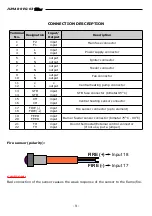
THE CONNECTION DIAGRAM
The figure above shows a scheme demonstrating connection of sensors and controlling
elements to the controller. Before connecting the regulator to network, it is necessary to
check all the connections carefully. One has to take particular note of not placing ~230V
power supply cables instead of the sensor. Improper connection may permanently
damage the microprocessor device.
- 8 -
`
IG
N
IT
E
R
~
2
3
0
V
F
E
E
D
E
R
~
2
3
0
V
~
P
O
W
E
R
S
U
P
P
L
Y
~
2
3
0
V
F
U
S
E
4
A
T
T
C
H
S
E
N
S
O
R
S
T
B
F
U
S
E
G
A1
A2
F
A
N
~
2
3
0
V
C
H
P
U
M
P
~
2
3
0
V
F
E
E
D
E
R
S
E
N
S
O
R
F
IR
E
S
E
N
S
O
R
R
O
O
M
T
H
E
R
M
O
S
T
A
T
T
Summary of Contents for REG-03 Mini
Page 2: ...JUMAR REG 03 Mini 2...
Page 31: ...JUMAR REG 03 Mini NOTES 31...


