– 27 –
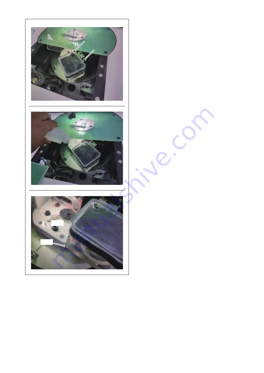
MAX
❻
❼
MIN
3) Remove lubricating rubber
. Pour the sup-
plied oil (or specified oil) into the oil tank.
4) The proper amount of oil in the oil tank is be-
tween the Min and Max marker lines indicated on the oil tank.
Page 1: ...PS 900 13090 INSTRUCTION MANUAL...
Page 2: ...centricity How to handle the case where you have checked the timing between the needle entry and the hook as described in 3 1 10 and have found it is not correct 18 3 2 Installing the bobbin winder de...
Page 3: ...ermediate presser stroke 47 4 18 Adjusting the needle thread air blower 48 4 19 Making a template 49 4 20 Preparation for sewing 51 4 21 RFID How to use the electronic label 53 4 22 Configuration of t...
Page 4: ...8 kg Laser type 762 kg Without packaging Standard type 575 kg Laser type 649 kg 19 Dimensions 2 100 mm W 2 325 mm L 1 240 mm H 20 Operating temperature range 5 to 35 C Laser type 1 to 35 C 21 Operatin...
Page 5: ...of revolutions for sewing 3 000 sti min Number of revolutions for sewing at shipment 2 800 sti min Maximum applicable number of revolutions for sewing at each pitch Pitch Number of Revolu tions Pitch...
Page 6: ...hine head Table X axis feed mechanism Y axis feed mechanism Cassette clamp device Operation panel Air control box Electrical control box Power switch also used as the emergency stop switch Thread stan...
Page 7: ...ne 3 1 1 Unpacking 1 Lift clamp as shown in the picture 2 Detach top cover first Then detach the remaining covers from the four surfaces If the clamp is not lifted up sufficiently unpacking will not b...
Page 8: ...s and feed mechanism from the wooden crate Insert the forks of the forklift into this portion 4 Remove front and rear sheet metal fittings for fixing the sewing machine Tools are packed in the accesso...
Page 9: ...orizontal ly on the forks of the forklift Keep the sewing machine on the forks in such a way that it does not rattle 3 1 2 Setting up the X feed mechanism 1 Detach clamping plates Put the screws and n...
Page 10: ...echanism 4 Detach rubber plug Remove four nuts on the opposite side with a wrench key Take care no to allow the screws to slip off the mounting holes after you have removed the nuts Put the nuts you h...
Page 11: ...thread stand to the machine head at the front side of the sewing machine See below for how to change the installation position of the thread stand 2 Threading method 1 In the case you have installed t...
Page 12: ...d to the front side of the sewing machine 1 Remove the thread stand asm 2 Remove the sheet metal as shown in the figure and attach the thread stand asm to the sheet metal Lastly attach the relevant pa...
Page 13: ...ght and front center tables Tighten the screws as illustrated in Fig 1 X feed mechanism Table Check for a clearance After you have set up the right and left sub tables check to make sure that there is...
Page 14: ...e packed in the accessory box for the sewing machine 1 Secure the bobbin thread winder to the aluminum frame of the front table right with T head screw A and nut B B B A A 2 Set up the front tables le...
Page 15: ...Secure the switch button asm so that its three switch buttons are faced upward B B A A 4 For the laser type model also change instal lation of the power switch as shown in the figure Changes described...
Page 16: ...and pneumatic components are correctly assembled 3 Inspect whether the needle entry point is cor rectly aligned with the center of the needle hole in the throat plate of the sewing machine 4 Inspect...
Page 17: ...blown directly to the human body Then carefully open the air cock 2 Adjustment of air pressure Pull up air regulating knob Then turn it to adjust the air pressure to 0 5 0 6 MPa Then push down air re...
Page 18: ...ality of the air supply When the supply air contains a considerable amount of moisture Ambient environment When our machine is installed at a place where the temperature greatly changes in the morning...
Page 19: ...First remove the auxiliary disk presser and the intermediate presser Check the alignment of the needle entry point of the sewing machine with the center of the throat plate Check the direction of 360...
Page 20: ...to rotate the needle bar 1 Press Next Page on the Main screen to display the maintenance screen 2 Press Extend to display the Extension screen 3 Press and to rotate the needle bar and the hook driving...
Page 21: ...ment of their positions in four directions 0 90 180 and 270 1 Remove two resin covers eye protection cover and presser foot Throat plate 3 Reset the hook driving shaft saddle to the 0 position 4 Atta...
Page 22: ...alf i e x 2 mm Refer to 3 1 11 2 How to adjust the position of the hook driving shaft saddle p 20 Adjustment of the hook driving shaft saddle and the needle bar in longitudinal direction 13 Similarly...
Page 23: ...ws 2 Turn the hook driving shaft saddle and remove two screws With a 3 mm hexagonal wrench key Screws Screws 3 Turn the hook driving shaft saddle Remove two screws and take remove the metal plate With...
Page 24: ...r side to move the hook driving shaft saddle back and forth After the adjustment tighten the screws de scribed in the step 5 and tighten the two screws on the near side For example when you want to ad...
Page 25: ...areful not to mix up the right and left metal plates Before energizing the sewing machine turn the hook driving shaft saddle by hand to make sure that the sensor detection plate does not come in conta...
Page 26: ...eep parameter 4 key numbers from 0 to 9 5 key numbers from 9 to 0 6 key turn left 7 key turn right 2 Indicator light 1 Parameter indicator light 2 Production failure indicator light 3 Stop indicator l...
Page 27: ...eyond the sewing machine table in X direction Take care not to allow the machine to hit against someone standing near the table to cause inju ry 2 Be sure to secure a space as wide as 500 mm or more a...
Page 28: ...ss switch 2 Cylinder lifting plate comes off upward Remove it The cylinder pushes up the lifting plate 3 To install cylinder lifting plate press switch The cylinder comes down to allow the cylinder li...
Page 29: ...the sewing machine Display A Display B Display C 1 Detach cylinder lifting plate 2 Remove cylinder lifting plate Press on the Start screen A to display the screen B Then press to display the screen C...
Page 30: ...MAX MIN 3 Remove lubricating rubber Pour the sup plied oil or specified oil into the oil tank 4 The proper amount of oil in the oil tank is be tween the Min and Max marker lines indicated on the oil t...
Page 31: ...old the needle so that its groove faces toward blade point of the rotary hook 2 Tighten screw In the case of replacing the needle with a needle which differs in specifications be sure to re adjust the...
Page 32: ...achine thread on thread stand 2 Pass the thread as illustrated in the figure Insert the tip of the thread into the hole in upper rubber of the needle bar 3 Press Threading switch located at the lower...
Page 33: ...pull the thread as it is By so do ing the thread will pass under the tension spring and be pulled out from thread hole C 3 Pull out the thread by 50 mm from thread open ing C Check the position of yo...
Page 34: ...the material Fig A If the thread tension is excessively high when sewing a light weight material the material may become wrinkled or thread may break Adjust the tension by changing A and B The adjust...
Page 35: ...illustrated in the figure A B 3 Method for using the AT 1 Method for setting the AT thread tension 1 Select the sewing pattern thread tension for which you want to set 2 Press presser foot thread ten...
Page 36: ...om 1 to 100 integers only 2 To set the default tension just check the appropriate tension by trial sewing and set tension 1 during production 2 Method for changing the thread tension dur ing sewing 1...
Page 37: ...sion from the first changing point 60 Thread tension from the second changing point To the end of sewing 30 60 Be sure to set the thread tension in this entry field when you want to change the thread...
Page 38: ...counterclockwise to decrease it 4 Adjusting the thread breakage detector plate Loosen setscrew Adjust the position of thread breakage detector plate so that the amount of contact between thread breaka...
Page 39: ...ove the thread being tangled in the hook carefully Then re start sewing WARNING Turn OFF the power before starting the work so as to prevent accidents caused by abrupt start of the sewing machine 1 Ne...
Page 40: ...le bar Then tighten the nee dle bar connection collar setscrews After you have assembled the relevant parts check to make sure that there is no gap at the top and bottom of the needle bar connection 2...
Page 41: ...veral turns clockwise 5 Press button to start winding thread on the bobbin 6 When the bobbin thread amount wound on the bobbin reaches the set amount 80 the bob bin winder automatically stops turning...
Page 42: ...needle bearing of the thread trimmer connecting rod with groove in the thread trimming cam The shipping standard of the electrical shaft an gle setting parameter QEP value is 170 Finely adjust this p...
Page 43: ...Then tighten fixing screw of the counter knife while aligning the tail section of the counter knife with the hexagonal wrench 3 Loosen setscrew of the moving knife rod Adjust the clearance provided b...
Page 44: ...counter knife pressure adjustment screw two locations After the completion of the aforementioned ad justment face down the moving knife and re ad just the moving knife pressure repeatedly until both...
Page 45: ...ing out the procedure described below confirm the state that the needle thread from the thread take up lever to the needle and the bobbin thread are removed the presser foot is lifted and the slide pl...
Page 46: ...quantity adjustment screw in the direction of arrow A to increase it Then adjust the hook oil quantity by turning the adjustment screw in the direction of arrow B to decrease it 3 The hook oil quanti...
Page 47: ...of the throat plate can be finely adjusted with screws and 1 Loosen screws and and lightly loosen screw Then move the throat plate to adjust so that the needle is aligned with the center of needle ho...
Page 48: ...resser Check the actual sewing operation Use the disk presser or the plastic disk presser according to the condition of actual sewing operation A Disk presser factory attached at the time of shipment...
Page 49: ...or underside of material Change over the setting of the wiper function be tween ON and OFF in accordance with these two conditions of the needle thread end position To put the needle thread end on th...
Page 50: ...ending on thickness or type of the material 1 Press on the main screen of electrical box 2 When you press the Machine setting parame ter is displayed When you enter the password 11111111 screen is dis...
Page 51: ...to allow the thread end to be pushed by air Launch the pattern creation software to operate and process the pattern to be sewn On the screen that is displayed by clicking Op eration processing click E...
Page 52: ...ing to the complexity of the pattern Locus of sewing slits on the template should be designed according to the pattern to be sewn or intend ed machining Select the suitable pattern carving machine The...
Page 53: ...wer templates are aligned Affix exclusive template tape 36 mm wide to portions and as illustrated in the figure 2 To produce more beautiful seams it is recom mended to firmly secure the material at th...
Page 54: ...Manual for the comput er control system for details 5 Attaching a pattern Moving an empty pattern with no material fit positioning hole A on the pattern positioning plate on the positioning pin Fit ot...
Page 55: ...Place the material to be sewn on the pattern Then check that the material is neatly arranged horizon tally In addition secure the material with the holding method that matches the pattern to prevent t...
Page 56: ...Attaching the electronic label Attach electronic label onto the pattern with double sided adhesive tape or the like 2 Writing sewing pattern data 1 Place electronic label on black dot on the sewing m...
Page 57: ...agement on the menu screen 4 Select sewing pattern data you want to write on the electronic label on the memory file screen After you have made a selection press RFID to write the sewing pattern data...
Page 58: ...n data 1 On the initial screen press the Self lock button 2 Place the electronic label with the sewing pat tern data written on it on the black dot on the table 3 The sewing pattern data written in th...
Page 59: ...ily stop sewing C OPEN key Move the cylinder lifting plate up and down D PRESS key Used to move up down the cassette holder E START key Used to start sewing F USB port G Reset button Used to re start...
Page 60: ...d to move the screen to the presser foot setting screen 1 Page move key Used to move the screen to the test mode screen 1 Test key Used to operate the sewing pattern by jumping Line segment return key...
Page 61: ...uration of use of the sewing machine has reached the time requiring maintenance is provided in order to extend the product life of the sewing machine Under this mode the maintenance screen is displaye...
Page 62: ...screen keep the clamp foot held at its current position while moving the shaft Lifted or lowered The Main screen is displayed after the operation panel is started up P259 Automatic operation of the c...
Page 63: ...stitch sewing speed P170 Number of revolutions of the reverse feed stitching r min 100 to 3000 1200 Reverse feed stitching speed P13 Whether or not the soft start is required Yes No Yes Whether the m...
Page 64: ...10 Thread clamp ON angle at the begin ning of sewing P26 Thread clamp ending angle at the beginning of sewing 1 to 990 10 Thread clamp OFF angle at the begin ning of sewing P27 Thread clamp starting...
Page 65: ...ot is not lifted during temporary stop Yes No No Statistics settings P49 Bobbin thread remain ing amount is cleared at the time of turning the power ON Yes No No Whether the remaining amount of bobbin...
Page 66: ...age output IO Yes No No Thread breakage setting P60 The number of revo lutions of the thread trimmer main shaft r min 10 to 500 260 Thread trimmer main shaft speed P61 Delay in the start of thread tri...
Page 67: ...ng point of the machining file Default The sewing machine stops after the completion of machining P395 Template recognition method Barcode elec tronic label Electronic label By serial number of file B...
Page 68: ...encoder is dam aged 3 Power board is broken 4 The motor is broken 1 Check the wiring of the main shaft en coder 2 Replace the main shaft motor 3 Replace the power board 4 Replace the motor E020 X axis...
Page 69: ...e Spare alarm E028 X axis AD sampling module failure 1 Abnormal startup 2 The motherboard is damaged 1 Restart 2 Replace the motherboard E029 X axis overheated Drive overload Lighten the load E030 Y a...
Page 70: ...are alarm E038 Y axis AD sampling module failure 1 Abnormal startup 2 The motherboard is damaged 1 Restart 2 Replace the motherboard E039 Y axis overheated Drive overload Lighten the load E040 Z axis...
Page 71: ...overload Lighten the load E060 Main shaft overvoltage 1 The mains voltage is too high 2 Power board failure 1 Check the internal drive to preview whether the main shaft voltage is higher than 400V ch...
Page 72: ...vo motor 3 Replace Y servo board E074 Y servo encoder AB inter ference 1 The Y servo board program is the old version 2 Poor contact or broken wire of the servo encoder 1 Look at the screen Internal D...
Page 73: ...se quence error Incorrect wiring phase sequence Wiring in the correct phase sequence E088 Y servo driver Rated cur rent input error Spare alarm E089 Y servo brake resistor over load Spare alarm E090 Y...
Page 74: ...it ed 2 The motor is stuck 3 The power board main shaft mod ule is damaged 1 Check and replace the motor 2 Check the machinery 3 Replace the power board E113 Broken main shaft encoder 1 Poor contact o...
Page 75: ...oard program is the old version 2 Mechanical stuck 1 Internal drive main shaft no version number means that the old version needs to be returned to the factory to update the program 2 Check the machin...
Page 76: ...2 Replace the power board E205 Pressure box didn t put down The current frame is in the raised state Click the Frame button to lower the press frame E206 Failure of head board 1 Bad head cable 2 The...
Page 77: ...func tion such as lifting IO 6 Replace the motor 7 Check the line replace the driver E213 Broken line 1 The sewing thread is broken 2 Disconnection detection device failure 3 Parameter error 1 Thread...
Page 78: ...s BP01 system can only upgrade BP01 program 2 Confirm whether the upgrade file in the USB flash drive is damaged E221 Upgrade file type error The upgrade file is corrupted or the upgrade file is not s...
Page 79: ...e or change screen E233 File error An error occurred while reading or writing from the USB flash drive 1 Replace graphics files 2 Re insert U disk or replace U disk E234 Graph or head offset out of bo...
Page 80: ...the frame E248 Auxiliary frame is not pressed down 1 Unpressed auxiliary pressure frame 2 Parameter setting error 1 Click the corresponding IO button of the auxiliary pressure frame 2 Reset parameter...
Page 81: ...sconnected 2 The motor is damaged 3 The motherboard is damaged 1 Check the encoder cable of the driver board 2 Replace the motor 3 Replace the motherboard E408 0x Driver board encoder AB interference...
Page 82: ...Driver board bus volt age phase loss Refer to E086 Error Handling Method E421 0x Drive board motor phase sequence error Reverse phase sequence Measure with a multimeter to restore the correct phase se...
Page 83: ...r board electronic gear ratio range Refer to E110 Error Handling Method E445 0x Driver board input pulse frequency is too high Refer to E132 Error Handling Method E446 0x Driver board motor overheatin...
Page 84: ...The hardware is damaged result ing in too small resistance 1 Buck treatment 2 Replace the hardware E473 0x Driver board software overcurrent Refer to E023 Error Handling Method E474 0x Driver board en...
Page 85: ...a tool such as an air gun In particular clean up the regions in which the aforementioned thread waste thread end and other stains are likely to remain Eight hours 2 Apply grease to the upper and lowe...
Page 86: ...ank drops below the low er scale marker replen ish the oil tank with the accessory or specified 10 oil Display A 2 Press on the Start screen A to display the screen B Then press to display the screen...
Page 87: ...4 Adding the lubricating oil to the gear box 1 Press on the Start screen A to display the screen B Then press to display the screen C On the screen C press and to rotate the bed and move lubricating r...
Page 88: ...ace in the gear box can be checked through the oil sight window on the side face of the frame Stop pouring of the lubricating oil when the oil surface reaches the center part between the H and L lines...
Page 89: ...tion straight Thread guide plate has a long thread guide under it so be careful not to allow the thread guide to hit against the surrounding parts to protect against breakage 4 Remove dust from the ho...
Page 90: ...rating time 5 Air gun 6 After the completion of installa tion of the parts check whether or not the threading air blow is normal If necessary adjust the threading air blow by changing the mounting pos...
Page 91: ...optional needle cooler Check the rough state of needle tip Use the ball pointed needle 3 The needle often breaks The needle is bent The needle comes in contact with the intermediate presser The needle...
Page 92: ...d at the tip of needle can be clamped with the disc presser 9 The needle thread is entangled in the inner hook holder The clearance provided between the inner hook holder and the inner hook is too sma...
Page 93: ...tery following the local laws and regulations How to remove the battery 1 Release lock of the door at the back or side face of the sewing machine to open the door 2 Remove cover setscrews of electrica...
Page 94: ...nnect the plug of the bar code reader to the panel When bundling the barcode cable slightly loosen the cable near the barcode reader No Part number Part name Quantity 40269588 Barcode reader assembly...
Page 95: ...e barcode seal to the cassette at the posi tion that is 250 mm left from the center of cassette setup guide and 30 mm below the upper side of cassette The aforementioned sticking position is recommend...
Page 96: ...nge D from Electronic identification label to Barcode Then press E 2 Setting the barcode functions Setting the barcode functions on the oper ation panel 1 Press button A 2 Press button B In the defaul...
Page 97: ...94 E F G 5 Return to the screen of 2 Press button E 6 Press button F 7 Press button G The password is 11111111 8 Set the mode to 0...
Page 98: ...95 A Setting the barcode number 1 Press button A 2 Press button B 3 Select the sewing pattern file you want to read and press button C 4 Press button D Save the data B D C...
Page 99: ...the pattern is converted appropri ately If the barcode reader does not beep adjust the vertical position of the barcode reader If the pattern is not converted even when the barcode reader beeps check...