−
14
−
②
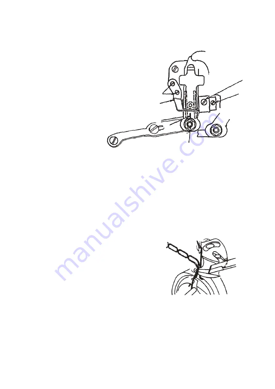
Adjust so that the center of moving knife link pin
is aligned with V groove (Fig. 15 (2)) of the center
of slot in knife driving arm (Fig. 15 (3)), and tighten
the lock nut to fix the pin.
③
Loosen two setscrews (Fig. 15 (4)) in driving arm
stopper (Fig. 15 (5)).
④
Move knife driving arm (Fig. 15 (2)) so that V
groove (Fig. 14) on the knife installing base is
aligned with the periphery of moving knife, press
it to driving arm stopper (Fig. 15 (4)) at that
position, and tighten setscrews (Fig. 15 (5)).
⑤
Loosen the respective two setscrews in thread trimmer cam (Fig. 15 (7)) and cam collar (Fig. 15 (6)).
⑥
Align marker dot (red : Fig. 13 (2) or green (3)) on the handwheel with marker dot (Fig. 13 (1)) on the
machine arm.
⑦
Turn with finger top setscrew No. 2 (Fig. 15 (7)) in the thread trimmer cam so that it comes to this side, and
press the thread take-up picker to the right when the setscrew comes to this side.
⑧
Move the cam to the right and left to engage the cam with the roller.
⑨
In this state, lightly pulling the cam to the right, move it in the direction of arrow (this side) until it will rotate
no further.
⑩
Temporarily tighten setscrew No. 2 (Fig. 15 (7))
in the cam.
⑪
At this time, check the following matters :
a) Marker dot on the handwheel is aligned with
that on the machine arm.
b) Roller smoothly enters the groove in the cam.
c) Amount of recession of knife is 2.5 to 3 mm
(SH : 3 to 3.5 mm).
⑫
Securely tighten two setscrews in the cam.
⑬
Press cam collar to the cam, and tighten one
setscrew.
[Caution]
○
Amount of recession of knife is largely affected even when adjustment of left and right
positions of moving knife link pin is finely performed.
○
Check whether moving knife handles thread as shown in Fig. 16.
(1)
(5)
(4)
(3)
(6)
(7)
(2)
Fig. 15
Fig. 16


