background image

– 17 –

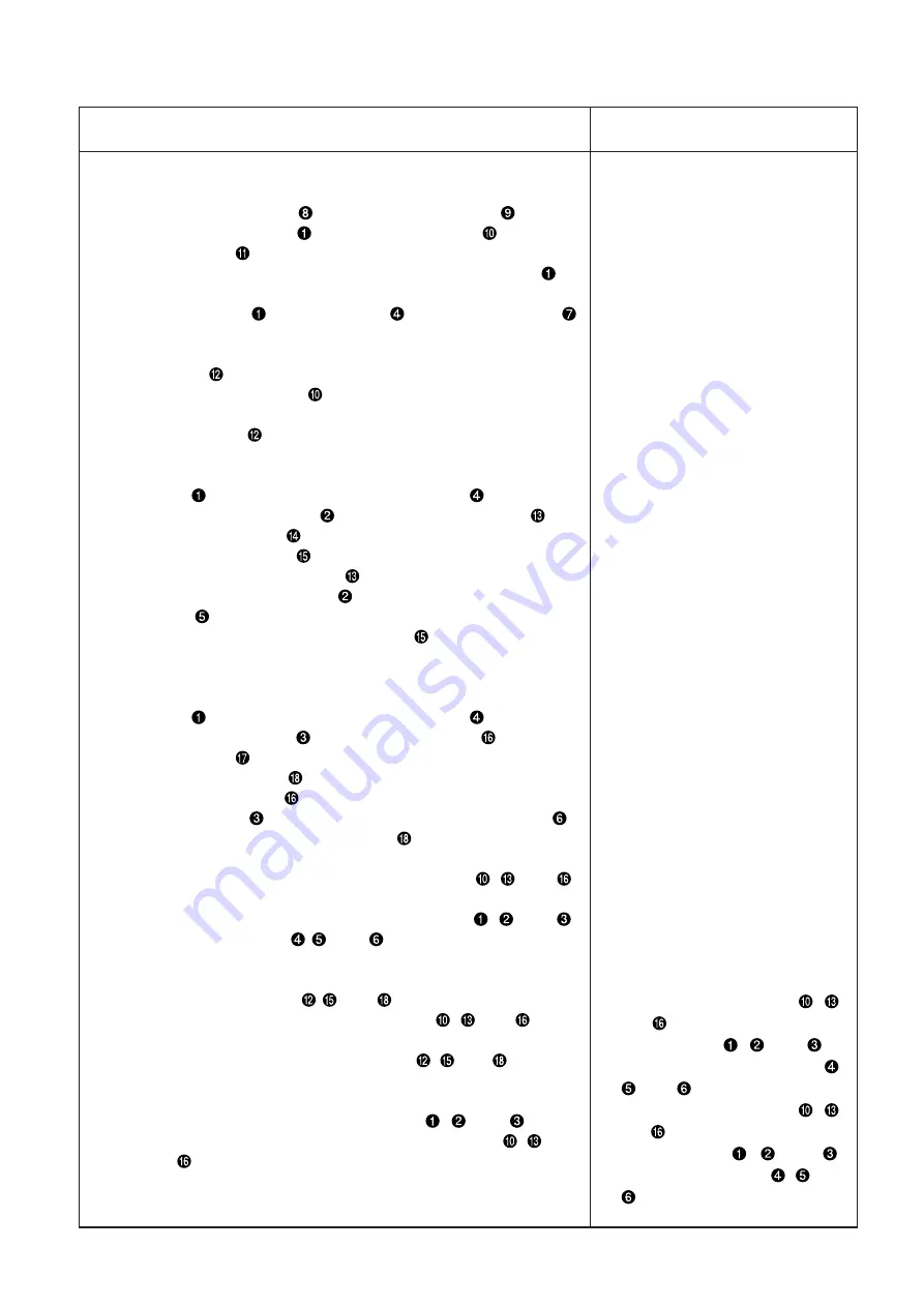
1) Looper return
(1) Front looper

1. Loosen the setscrews 

 to remove the throat plate 

.

2. Mount the front looper 

 on the front looper base 

 and tighten

the setscrew 

.

3. Rotate the pulley counterclockwise, move the front looper 

to

the most left position, and measure the clearance from the tip of
the front looper 

 to the left needle 

 with the looper gauge 

or a scale.

4. For adjusting the clearance to the standard distance, loosen the

setscrew 

 securing the front looper base to adjust the position

of the front looper base 

 in the right-left direction.

5. After adjustment, tighten the setscrew to secure the front looper

base setscrew 

.

(2) Middle looper

1. Rotate the pulley counterclockwise and align the tip of the front

looper 

 with the left surface of the left needle 

.

2. Mount the middle looper 

 on the middle looper base 

 and

tighten the setscrew 

.

3. Loosen the setscrew 

 securing the middle looper base and

move the middle looper base 

 in the right-left direction to align

the tip of the middle looper 

 with the left surface of the right

needle 

.

4. After adjustment, tighten the setscrew 

 to secure the middle

looper base.

(3) Rear looper

1. Rotate the pulley counterclockwise and align the tip of the front

looper 

 with the left surface of the left needle 

.

2. Mount the rear looper 

 on the rear looper base 

 and tighten

the setscrew 

.

3. Loosen the setscrew 

 securing the rear looper base and move

the rear looper base 

 in the right-left direction to align the tip of

the rear looper 

 with the left surface of the middle needle 

.

4. After adjustment, tighten the setscrew 

 to secure the rear looper

base.

(Caution) When the positions of each looper base (

, and 

)

are adjusted in the right-left direction, adjust the
clearances from the tips of the loopers (

, and 

)

to the needles (

,

, and 

) as well.

2) Adjustment of the clearance between the looper and needle

1. Loosen the setscrews (

,

, and 

) securing the looper bases

to adjust the positions of the looper bases (

, and 

) in the

front-rear direction.

2. After adjustments, tighten the setscrews (

, and 

) to secure

the looper bases.

(Caution) When the clearances are adjusted, check the looper

return positions for each looper (

, and 

) in the

right-left direction because the looper bases (

, and

) may move in the right-left direction.

o Insufficient or excessive looper

return may cause stitch skipping,

needle breakage, or thread

breakage.

o When each looper base (

,

and 

) is moved leftward, each

tip of loopers (

, and 

) is

detached from each needle (

,

, and 

).

o When each looper base (

,

and 

) is moved rightward, each

tip of loopers (

, and 

)

touches each needle (

, and

).

Adjustment Procedures

Results of Improper Adjustment

Summary of Contents for 35800 Series

Page 1: ...40052737 No E376 00 ENGINEER S MANUAL Feed off the arm 3 Needle Double Chainstitch Machine 35800 Series...

Page 2: ...rvices to be done on this sewing machine should be based on this manual This manual gives the Standard Adjustment on the former section under which the most basic adjustment value is described and on...

Page 3: ...motion paths 20 7 Adjustment of rear needle guide 22 1 Longitudinal adjustment of the rear needle guide 22 2 Height adjustment of rear needle guide 22 8 Adjustment of feed dog height and longitudinal...

Page 4: ...Adjustment of bobbin thread cam 40 17 Adjustment of tension disk rise 42 18 Adjustment of air nozzle air blow 44 19 Adjustment of folder 46 8 Lubrication 48 9 Folder types 49 10 Maintenance 50 1 Spare...

Page 5: ...rrow type narrow type wide type Main feed Slide type stitch pitch adjusting system Differential feed Differential feed lever adjusting system 1 piece feed lever adjusting system 16 Lubrication Automat...

Page 6: ...10mm Main feed Slide type stitch pitch adjusting system Differential feed Differential feed lever adjusting 1 piece feed lever adjusting 1 piece feed system system 16 Lubrication Automatic rotary pump...

Page 7: ...00DZ36 5 35800DRU8 6 35800DRU9 7 35800PZ32 8 35800PZ36 9 35800DWW8 10 35800DWW9 No Model Application Double lap seam denim denim fabric of 6 to 9 oz working clothes working pants etc For light weight...

Page 8: ...MEMO 4...

Page 9: ...Double lap seam For medium and heavy weight materials denim fabric of 10 14 oz 2 4 mm of throat plate unevenness Standard type wide roller equipped Denim jacket work ing clothes etc WDR Same as above...

Page 10: ...BWW 8 3 3 2mm BWW 9 3 3 6mm DWW 8 3 3 2mm DWW 9 3 3 6mm 4 Description of model code Machine name Feed off the arm 3 needle double chainstitch machine 1 2 3 4 5 6 7 8 9 10 11 12 13 14 15 3 5 8 0 0 A A...

Page 11: ...pection window rear Cylinder side cover Right and left guide plates Thread tension knob Gauge plate Guide finger Thread guide Feed rocking lever eccentric pin Roller pressure regulating spring Oil cir...

Page 12: ...r left needle thread 2 for middle needle thread 3 for right needle thread Looper 4 for front looper 5 for middle looper 6 for rear looper Follow the drawing below to pass the threads 4 3 2 1 5 6 5 6 4...

Page 13: ...dle thread 1 for left needle thread 2 for middle needle thread 3 for right needle thread Looper 4 for front looper 5 for middle looper 6 for rear looper Follow the drawing below to pass the threads 2...

Page 14: ...mbly roller pressure regulating screw and pressure regulating plate spring assembly before adjustment Caution The directions of front rear right and left during standard adjustment are based on the op...

Page 15: ...slightly 5 Loosen the pressure regulating nut and remove the pressure regulating plate spring assembly 6 Loosen each setscrew that securing corresponding needles and remove three of each needle 7 Loo...

Page 16: ...the pulley in both directions to check the clearance The allowable clearance range is from 0 to 0 1 mm Caution The allowable clearance between the steel rod and the throat plate ranges from 0 to 0 1 m...

Page 17: ...surface of the lower needle bar bushing may touch the top surface of the timing gauge ahead of the other touch In such a case make sure that the clearance between the steel rod and the throat plate i...

Page 18: ...tion The standard needle entry position in the front rear direction is decided under the condition that the clearance between the needle and needle hole of the throat plate B is the same for all of 3...

Page 19: ...needles touch evenly 2 Needle entry adjustment 1 For adjusting the needle entry position in the right left direction remove 6 setscrews securing the front top cover to remove the front top cover and...

Page 20: ...looper the looper return is adjusted with the gauge and a scale and for the middle and rear loopers and the looper return is adjusted by aligning the tips of the middle and rear loopers and with the...

Page 21: ...he front looper with the left surface of the left needle 2 Mount the rear looper on the rear looper base and tighten the setscrew 3 Loosen the setscrew securing the rear looper base and move the rear...

Page 22: ...the left needle to 1 6 mm Caution For adjusting the needle bar height select an easier to adjust one from either 1 or 2 mentioned above 3 Checking of the middle and rear looper heights shall be also c...

Page 23: ...ion vertically 3 After adjustment tighten the setscrew Caution Use caution not to rotate the needle bar at adjustment of needle bar height Failure to observe this changes needle entry positions o Rema...

Page 24: ...er 2 For the middle and rear loopers and the standard position for each is decided under the same condition as the front looper i e the tips of the needles and touch the rear of the loopers at 1 4 fro...

Page 25: ...nt and rear momentum amount of the looper move the ball joints and upwards o When increasing the front and rear momentum amount of the looper move the ball joints and downwards Caution 1 When the fron...

Page 26: ...the respective needles and according to the needle entry position Recheck the needle entry condition for adjustments if the contact positions of the right and left needles and seem to be different 2 T...

Page 27: ...y clearance is perceived readjust the related conditions 2 Height adjustment of rear needle guide 1 Loosen the setscrew and move the rear needle guide base vertically to adjust the height 2 After adju...

Page 28: ...ction of the throat plate to the front section of the main feed dog in position where the main feed dog stays in the most advanced position Clearance D is defined as the distance from the feed groove...

Page 29: ...oosen the setscrew of the main feed rocking lever link and turn the main feed rocking eccentric drive stud to adjust the throat plate not to contact the feed groove front rear section After adjustment...

Page 30: ...ount the standard positioning is secured when Clearance A and Clearance B are equalized Clearance A is defined as the distance from the feed groove front section of the throat plate to the front secti...

Page 31: ...oosen the setscrews and and remove the plug female screw 2 Using a screwdriver turn the eccentric pin clockwise and counterclockwise until the front and rear positions of the main feed dog are properl...

Page 32: ...h has been changed check 7 Adjustment of rear needle guide and make a proper readjustment 2 Adjustment of differential feed amount The amount of differential feed can be adjusted by moving the differe...

Page 33: ...l adjusting lever is advanced in the reverse differential direction 1 to 4 the differential ratio is decreased and the sewed materials are extended o When the differential adjusting lever is retreated...

Page 34: ...m above the upper face of the throat plate before the upper feed roller begins to rise Caution 35800BWW DWW The maximum amount of rise is 10mm for extra heavy materials 2 Adjustment of presser bar pre...

Page 35: ...hen the above mentioned adjustments are made the connecting positions shall be secured for the lifter lever with slide hole and the lifter lever by moving the lifter lever with slide hole in the right...

Page 36: ...d front rear and right left clearances shall be uniform between the upper feed roller and the feed dog 3 The standard positioning of the upper feed roller shall be free from right and left rattling pe...

Page 37: ...de finger is put on to keep contact with the upper face of the guide support block 3 In the state as seen from behind confirm that the vertical clearance of the upper feed roller is maintained at the...

Page 38: ...th the throat plate and the feed dog should also be replaced Rear direction Screw contact face Key groove Front direction Feed roller support arm left No Name US Part No JUKI Part No 1 Standard type n...

Page 39: ...ort arm left Tighten the setscrew after confirming that there is no rattling on the right and left and light revolution seems to be secured Tighten the remaining setscrew Caution The upper feed roller...

Page 40: ...r the upper feed roller is defined to cause a slight pulling force for the sewing length 8 stitches inch of the feed dog The clutch connecting lever and the clutch set are connected The amount of draw...

Page 41: ...e clutch connecting rod is lowered the amount of draw for the material cloth is decreased o If the amount of draw for the upper feed roller is too much in conjunction with the sewing feed amount the n...

Page 42: ...ion shall be 36mm from the hole bottom C of the needle thread guide to the hole bottom D of the needle thread adjusting thread path 2 Height of rocking take up path The standard dimension is 15mm from...

Page 43: ...needle thread guide adjuster 1 Let the lever thread path stay at the lower dead point 2 Loosen two setscrews of the needle thread holding adjuster and move the needle thread holding adjuster verticall...

Page 44: ...d the first setscrew of the bobbin thread cam and another first setscrew of the pulley are aligned to the same line Caution When two main shaft setscrews and of the pulley are turned counterclockwise...

Page 45: ...of bobbin thread cam adjustments do not move the bobbin thread cam to the right and left If it is moved to the right and left the bobbin thread cam may come in contact with the right left side face o...

Page 46: ...tension disc when the upper feed roller rises by 1 0mm above the upper face of the throat plate and that the upper tension disc keeps floating when the upper feed roller rises further The standard siz...

Page 47: ...lift lever Then turn the tension floating shaft clockwise 2 Adjust height of the disc floating pin to 6 5mm and tighten the setscrew o If proper positioning is not secured for the disc floating pin t...

Page 48: ...nozzle is such that it is in parallel to the throat plate Standard forward and backward positioning is that there is no contact when the presser israised Height of the nozzle is about 23mm from the t...

Page 49: ...and turn the air nozzle to the right and left for adjustment 3 To adjust the front and rear positioning for the air nozzle loosen the setscrew and move the air nozzle forward and backward for adjustm...

Page 50: ...ont section A of the presser and the outlet section B of the upper folder Caution If Section B of the upper folder is installed as closer as possible to Section A of the presser the result of sewing t...

Page 51: ...by moving the tip of the upper folder to the right and left o To widen the outlets of the upper and lower folders and move the tip of the upper folder to the left o To narrow the outlets of the upper...

Page 52: ...on the completion of oil drainage tighten the oil drain front and rear screws and Caution To confirm the amount of oil at the oil gauge rear check the crest point of the oil level indicator that is ac...

Page 53: ...tandard type provided with a spring suitable for a product that has step sections in the material cloth Stanadard Same as the standard type The outlet section at the folder tip is narrow and suitable...

Page 54: ...BXW9 35824DQW9 35805BRWH9 35818CB9 35826X 23420AY 18 1 8 30516306 30059406 30526800 30541502 30515704 24502502 35830DWW8 35824DX8 35818CB8 30530307 30376206 24743304 35830DWW9 35824DX9 35818CB9 305296...

Page 55: ...0530307 30376206 24743304 35830DWW9 35824DX9 35818CB9 30527606 30376305 30541502 Feed method feed dog Roller feed mechanism 10 35800DZ Differential feed Clutch 11 35800PZ 1 piece feed Clutch 9 35800DR...

Page 56: ...ide roller Narrow roller Wide roller 29480BEB 29480BEA 29480BDY 29480BDZ Set 40057259 40057260 40057261 40057262 1 JUKI part No JUKI part No JUKI part No JUKI part No 22704 30103006 JUKI part No 35882...

Page 57: ...esulting in thead cut 1 4 Needle 4 A The needle is too thin Use an appropriate needle for the thread that is now used 1 5 Needle heat 5 A Thread cut occurs because Reduce the needle size Reduce the se...

Page 58: ...d the needle 3 3 Interference between 3 A The needle breaks because 6 Adjust the looper movement locus rear of lower looper of the strong interference Refer to the standard adjustment values and needl...

Page 59: ...d dog and contact level longitudinal position check Refer to the adjustment values 5 2 Chain stitch unthr 2 A Needle A 1 Needle bent or Replace the needle or mount eading mounting error the needle hol...

Page 60: ...e standard adjustment values 4 C Pressure regulating C 1 Insufficient pressure Adjust the presser bar pres spring of upper adjustment sureproperly feed roller 4 D Upper feed roller D 1 Insufficient dr...

Page 61: ......

Reviews: