1
H:\0 - Quality Documents\2 Department\Tech Serv\Application tooling\Presses\AP-K2N\TS010-00 AP-K2N Operation
Manual.doc
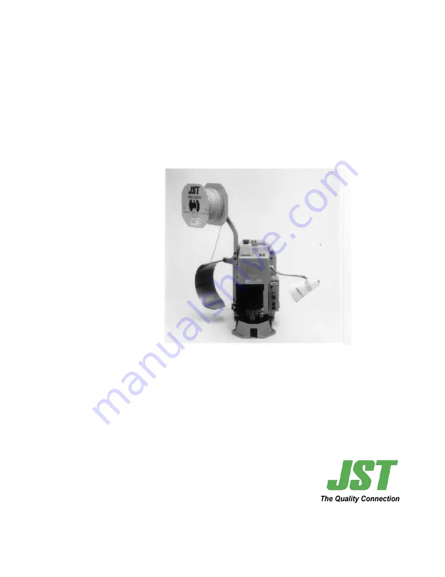
AP-K2N CRIMPING
MACHINE
OPERATION
MANUAL
This datasheet has been downloaded from
http://www.digchip.com
at this
page
Page 1: ...uments 2 Department Tech Serv Application tooling Presses AP K2N TS010 00 AP K2N Operation Manual doc AP K2N CRIMPING MACHINE OPERATION MANUAL This datasheet has been downloaded from http www digchip...
Page 2: ...ed tooling For safe operation THIS MACHINE IS A POWER PRESS AND SHOULD NEVER BE USED WITHOUT THE SAFETY GUARDS FITTED If you think that something is wrong with the machine immediately turn OFF the mac...
Page 3: ...Terminal Reel 7 3 4 Mounting the Safety Guard 8 4 CONTROL BOX CONFIGURATION 12 5 OPERATION 13 5 1 Manual Operation 13 5 2 Operation under Power 14 6 APPLICATOR 15 6 1 Terminal Feed Position Adjustment...
Page 4: ...adjustment Dial type Models MK L and MKF L for end feeding terminals and models MKS L and MKS LS for side feeding terminals The crimping machine utilizes a quick change system thus allowing quick chan...
Page 5: ...strates the footprint dimensions of the machine Secure the machine to the foundation with four M8 bolts The machine should be mounted so that the crimping dies are at the approximate eye level of a se...
Page 6: ...he protective rubber collar from under the dials on the applicator ram Step 3 Place the applicator on the base plate of the crimping machine Pull up the applicator ram whilst simultan eously pushing t...
Page 7: ...feed plate so that the pressure pad rises Feed the terminal strip between the guide rails Step 2 Place the first terminal at the correct crimping position Release the hook from the feed plate to allo...
Page 8: ...range of JST applicators WARNING AN AUTHORISED COMPETENT PERSON MUST ONLY CARRY OUT THE FOLLOWING OPERATIONS When using the MK L Applicator Step 1 Secure the fabricated steel guard JST UK 7 onto the A...
Page 9: ...p 2 Secure the die guard JST UK 6 onto the applicator using the cap head socket screws supplied Step 3 Select the appropriate side guard JST UK 3 and mount onto the side guard support bracket JST UK 9...
Page 10: ...to the side face of the applicator using the cap head screws supplied Step 3 Select the appropriate side guard JST UK 3 and mount onto the side guard support bracket JST UK 9 using the countersunk scr...
Page 11: ...upport bracket JST UK 9 using the countersunk screws supplied Step 3 Remove the two upper motor fixing screws and clamp the side guard support bracket onto the press utilizing these screws Step 4 Adju...
Page 12: ...ush button to restart If the Auto Power Off indicator illuminates just press the Power On push button to restart 4 Power On Push button green Indicator Lamp Press this button to turn on the motor The...
Page 13: ...he die parts have been installed incorrectly Step 1 Remove the cap head socket screws from the ram cover using the hexagon key supplied with the tool kit and open the belt cover Step 2 Manually operat...
Page 14: ...to 0 Step 4 Check that neither of the function indicators is illuminated then press the Power On push button green The motor starts running NOTE If a malfunction indicator is illuminated the motor wi...
Page 15: ...k the resultant crimped terminal If the appearance of the terminal is not correct repeat the above adjustment operation and check again When a satisfactory result is achieved replace the guards connec...
Page 16: ...h on the resultant crimp and re adjust if necessary When using the MKS L Applicator new type Move the entire feed plate to obtain the desired bell mouth crimp First loosen the feed finger retaining sc...
Page 17: ...n so a total range of 0 80mm is attainable We do not state insulation crimp heights due to the large variation of insulation types available The insulation should be set as per instructed in the JST C...
Page 18: ...e tooling has sustained damage please contact JST to either send back the tooling for repair or alternatively a JST Service Engineer can visit your company to repair the tool on site 6 6 Lubrication o...
Page 19: ...e a week CLUTCH SECTION Remove the cap head socket screws from the belt cover catch and open the cover Add a few drops of oil to the oiling points indicated on the photograph NOTE The frequency of lub...
Page 20: ...rease from all components of the clutch mechanism and sparingly lubricate all the clutch components with fresh grease Specified Grease Multemp PS no 1 manufac tured by Kyodo Yushi Co Ltd Do not use ge...
Page 21: ...by the noise it makes when crimping and also the measured crimp height of the terminal may become unstable Adjustment Procedure Step 1 Remove the two dome nuts from the side wall of the ram Step 2 Lo...
Page 22: ...Switch once 1 The connecting pin is broken 2 A solder joint on the 2 The Ram does foot switch metal plug 1 The Power Cord not move is bad is disconnected 3 The foot switch cord is damaged 2 The power...
Page 23: ...rmal Trip is activated Press in the thermal trip push button If the thermal trip has activated wait one minute or more before resetting Consult the JST Technical Department if the thermal trip activat...
Page 24: ...cord with a new one Connect the micro switch to the plug as per the illustration 4 The Clutch Spring has become slack or has broken Replace the spring with a new one 5 The Control Box is faulty The C...
Page 25: ...is defective The control requires repair Contact JST Technical Services Department for assistance 5 The Ram moves too slowly or stops at Bottom Dead Centre 1 A Stick Roller is worn out Replace the sti...
Page 26: ...26 H 0 Quality Documents 2 Department Tech Serv Application tooling Presses AP K2N TS010 00 AP K2N Operation Manual doc 9 EXPLODED VIEWS AND PARTS LISTS AP K2N Crimping Machine...
Page 27: ...27 H 0 Quality Documents 2 Department Tech Serv Application tooling Presses AP K2N TS010 00 AP K2N Operation Manual doc...
Page 28: ...28 H 0 Quality Documents 2 Department Tech Serv Application tooling Presses AP K2N TS010 00 AP K2N Operation Manual doc...
Page 29: ...112 Spring cap MA01 477 144 Pressure pad MA01 470 113 Spring block MA01 479 145 Feed plate 114 Spring MA01 480 146 Spring anchor MA01 350 115 Support pin MA01 343 147 Die block MA01 105 116 Stripper h...
Page 30: ...30 H 0 Quality Documents 2 Department Tech Serv Application tooling Presses AP K2N TS010 00 AP K2N Operation Manual doc...
Page 31: ...A03 105 146 Stripper bracket 113 Die plate MA03 104 147 Stripper 114 Side block MA03 107 148 Stripper screw 115 Support pin MA01 343 116 Feed plate base MA03 106 150 Guide plate R 117 Adj Plate MA03 1...
Page 32: ...32 H 0 Quality Documents 2 Department Tech Serv Application tooling Presses AP K2N TS010 00 AP K2N Operation Manual doc...
Page 33: ...15 Support pin MA01 343 152 E shaped ret ring 9 116 Spring post NF 4116 153 Guide block NF 4165 117 Plate L NF 4114 154 Holder block NF 4147 118 Plate R MA02 103 155 Pressure plate 119 Feed shaft MA01...
Page 34: ...34 H 0 Quality Documents 2 Department Tech Serv Application tooling Presses AP K2N TS010 00 AP K2N Operation Manual doc...
Page 35: ...haft LS 4315 316 Cam roller LS 4316 317 Pin LS 4317 318 Feed lever LS 4318 319 Feed lever pin LS 4319 320 Adj Screw 112 223 321 Feed finger spring MA01 348 322 Feed finger pin LS 4322 323 Hook LS 4323...
Page 36: ...36 H 0 Quality Documents 2 Department Tech Serv Application tooling Presses AP K2N TS010 00 AP K2N Operation Manual doc Notes...
Page 37: ...d Tel 66 2 693 2905 Fax 65 746 1787 G4 Fax 66 2 693 2906 Malaysia 1 Tel 60 0 3 755 4620 Indonesia 1 Tel 62 0 7 7061 1685 Fax 60 0 3 758 3802 Fax 62 0 7 7061 1684 Malaysia 2 Tel 60 0 4 226 7258 Indones...