36 | Operation
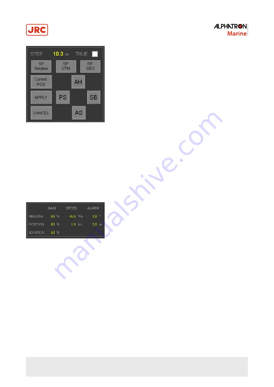
Figure 25: Position Settings section
•
Position Set point change STEP size in meters, parameter adjustable.
•
Select TRUE option for Absolute movement (N/E) and deselect button for Relative (X/Y) movement.
•
SP Relative, SP UTM, SP GEO to input new position Set Point.
•
Control button “Current Position” to use actual vessel location as Set Point.
•
Apply to confirm and execute the position Set Point change request.
•
Cancel to keep existing position Set Point.
2.3.1.5 Heading and Position Keeping Gain, Speed and Alarm Settings
The Gain Settings are displayed at the bottom of the MAP screen (Figure 26: Gain on page 36).
Figure 26: Gain
•
Heading Gain is amount of maximum thrust used for correcting heading.
•
Position Gain is amount of maximum thrust used for correcting position.
•
Joystick Gain is amount of maximum thrust used in Joystick Manual or Joystick Auto mode when joystick pushed in
outer position. See Joystick Gain Setting on page 36.
•
Speed maximum for rotation (°/m).
•
Speed maximum for movement (kn) (parameter adjustable).
2.3.1.6 Joystick Gain Setting
The system starts up in Joystick Manual. This mode can take full use of all thrusters. To limit the system to use less than
maximum thrust, the JSM GAIN setting is available. The joystick gain setting is used for both joystick modes; manual
joystick as well as auto joystick mode. See Heading and Position Keeping Gain, Speed and Alarm Settings on page
36.
The Joystick Gain (%) (parameter adjustable) value determines the amount of thrust supplied when the joystick or
rotation button is moved to most outer positions. (If set at 100% is full thrust). Advisable value in harbor is approximately
30%.
Summary of Contents for Alphatron Marine AlphaDynaPos
Page 1: ...AlphaDynaPos Ship Automation and Navigation system Operation Manual www jrc am ...
Page 5: ...5 Contents 4 2 Appendix B Checklist for Taking DP system into Operation 85 ...
Page 13: ...13 Introduction III 3 System Overview DP2 Figure 2 system Overview DP2 ...
Page 14: ...14 Introduction III 4 Sensor Overview Figure 3 Sensor Overview ...


