34 | Installation Instructions
1.7.2 Configuring the Gyro sphere
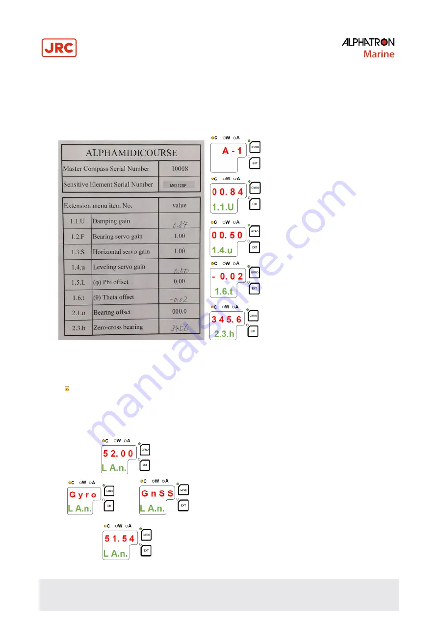
Each Sensitive element is tuned to its Master Compass before it is shipped from the factory. This tuning is reflected in a
set of parameters specific for this gyrocompass. These parameters are included in the sensitive elements package on
the Gyro sphere settings form. This parameter have to be entered into the Control Unit as part of the gyro compass
installation procedure. See below example form of AlphaMidiCourse gyrocompass with serial 10008.
The parameters are loaded into the Control Unit from the Extension menu as described below.
1) Enter the Extension menu by pressing and
holding the
SET
button and the
ACK/ENT
buttons simultaneously for approx. 3 sec.
Main category
A-1
will be displayed.
2) Press the
SET
button to enter the sub-
category loop. Sub-category
1.1.U
and its
parameter value will be displayed.
3) Use
▲
or
▼ to increase or decrease the
parameter value until the value is according to
the value of the form.
4) Confirm the entry by pressing
ACK/ENT
button and the display will return to the sub-
category.
5) Press
DISP
button again until you see
1.4.u
.
Repeat step 3 and 4.
6) Do the same for sub-category
1.6.t.
7) Press the
SET
button again to return to main
category
A-1
and then press the
DISP
button
to go to
A-2
main category.
8) Press
SET
button and enter the value for
2.3.h
,
2.5.y
(year),
2.6.N
(month and day),
2.7.t
(hour and minute) and
2.8.d
(total days
of operation. This value should be reset after
installation).
After step 8 is done return to the main category by pressing
SET
button and then exit the Extension menu by
pressing and holding the
SET
and
ACK/ENT
buttons simultaneously for approx. 3 seconds.
For more information about the Extension menu, see paragraph 1.8
Advanced Settings
.
Note
Values 1.1.U (Damping gain) and 1.6.t Theta offset are written on the Gyro sphere.
1.7.3 Setting the Latitude input source
When paragraph 1.7.2
Configuring the Gyro Spere
has been carried out the latitude input source can be changed as
described below.
1) Press the
DISP
button until the display shows latitude value.
2) Press
SET
button once and its upper line in the display starts flashing.
3) Use the
▲
or
▼ buttons for selecting
GYro
or
GnSS
as latitude input
source. Confirm the entry with
ACK/ENT
button.
-
When
GYro
is selected the display will change to flashing
numbers. Use the ▲
or
▼ button to set the latitude manually and
press
ACK/ENT
.
-
When
GnSS
is selected the display will show the latitude value
from GPS.
4) The display will return to show latitude value without flashing.
OR
Summary of Contents for ALPHAMIDICOURSE Mk2
Page 80: ...80 Appendices 6 1 1 Dimensions of Control Unit...
Page 81: ...81 Appendices 6 1 2 Dimensions of Master Compass...
Page 82: ...82 Appendices 6 1 3 Master Compass without housing...
Page 84: ...84 Appendices 6 1 5 Connection Diagram...
Page 85: ...75 Appendices 6 1 6 Cable Diagram...
Page 86: ...76 Appendices 6 1 7 Installation Drawing...
Page 88: ...78 Appendices AlphaMidiCourse Mk2 Check Maintenance Sheet...
Page 89: ...79 Appendices AlphaMidiCourse Mk2 Check Maintenance Sheet...
Page 90: ...80 Appendices AlphaMidiCourse Mk2 Check Maintenance Sheet...
Page 91: ...81 Appendices AlphaMidiCourse Mk2 Check Maintenance Sheet...
Page 92: ...82 Appendices AlphaMidiCourse Mk2 Check Maintenance Sheet...
Page 95: ...85 Appendices 6 4 Return Slip Sensitive element...
Page 96: ...86 Appendices...
Page 99: ......


