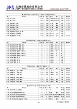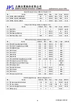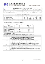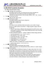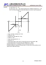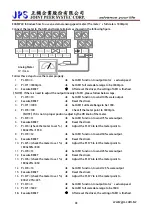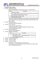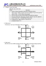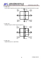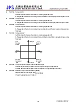
Example 2:
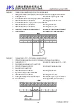
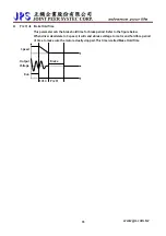
Simply using a variable resistor to set the running speed
1.
Wiring the variable resistor (VR) to control input terminals as the figure showed below.
2.
Setting Pr.233 = 0.
Î
Select AI1 input range (0 ~ 10V).
3.
Turn the VR to the maximum input position and read Pr.229.
4.
Write the Pr.229 value into Pr.230
Î
Setting AI1 maximum value.
5.
Turn the VR to the min. input position and read Pr.229.
6.
Write the Pr.229 value into Pr.231.
Î
Setting AI1 0V value.
7.
Write the Pr.229 value into Pr.232
Î
Setting AI1 min. value.
8.
Setting Pr.278 (Speed Command Select)=1
Î
Select AI1 input as speed command.
9.
Reset the driver.
Î
Change Pr.278, must reset driver.
VR
TM2
485B 485A
24V
ACOM
AM1
5V
AI1
ACOM
24V
Example 3:
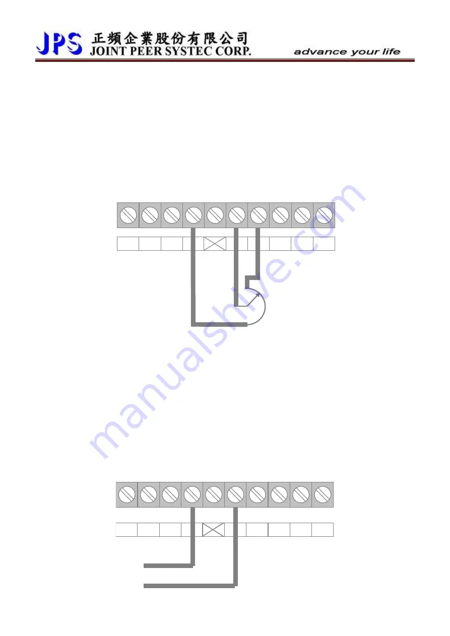
Using ex10V ~ -10V signal as speed command.
1.
Wiring the input signal lines to control terminals as the figure showed below.
2.
Setting Pr.233 = 1
Î
Select AI1 input range (-10V ~ +10V).
3.
Input maximum voltage to AI1, read Pr.229.
4.
Write Pr.229 value into Pr.230.
Î
Setting AI1 maximum value.
5.
Input 0V to AI1, read Pr.229.
6.
Write Pr.229 value into Pr.231.
Î
Setting AI1 0V value.
7.
Input min. voltage to AI1, read Pr.229.
8.
Write Pr.229 value into Pr.232.
Î
Setting AI1 min. value.
9.
Setting Pr.278 (Speed Command Select) =1
Î
Select AI1 input as speed command.
www.jps.com.tw
40
10.
Reset the driver.
Î
Change Pr.278, must reset driver.
+10V ~ -10V
0V
485B 485A
24V
ACOM
AM1
5V
AI1
ACOM
24V
TM2

