background image

Monterings- og bruksanvisningen må oppbevares under hele produktets levetid. These instructions must 
be kept for future references. Ce manuel doit être conservé pour de futures interventions. Wir empfehlen 
Ihnen, die Montage- und Bedienungsanleitung für spätere Zwecke sorgfältig aufzubewahren.

Jøtul F

S


165 - 

400

 FL


Manual V

ersion 

P02

Jøtul FS 

165


-

 I 

400

 FL

NO  

Monterings- og bruksanvisning 

 4

FI 

-  Asennus- ja kättöohje 

14

UK  

-  Installation and Operating Instructions 

23

FR 

-  Manuel d’installation et d’utilisation 

33

ES 

-  Manual de instrucciones 

42

IT 

-  Installazione e Istruzioni per l’uso 

52

DE 

-  Montage- und Bedienungsanleitung 

62

NL 

-  Installatie- en montagehandleiding 

72

Jøtul FS 

165

 - I 

400

 FL

Summary of Contents for FS 165-I 400 FL

Page 1: ...tung f r sp tere Zwecke sorgf ltig aufzubewahren J tul FS 165 I 400 FL Manual Version P02 J tul FS 165 I 400 FL NO Monterings og bruksanvisning 4 FI Asennus ja k tt ohje 14 UK Installation and Operati...

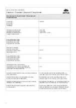
Page 2: ...ominel varmeafgivelse Verkningsgrad vid nominell v rmeavgivning Hy tysuhde nimellisl mp teholla 74 S rskilte forholdsregler n r ovnen monteres installeres eller vedlikeholdes S rlige forholdsregler de...

Page 3: ...llation ou l entretien de l appareil x Cualquier precauci n espec fica que deba tenerse en cuenta durante el montaje instalaci n o mantenimiento del equipo de calefacci n x Precauzioni specifiche da p...

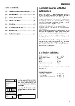
Page 4: ...burn chamber see installation manual for J tul I 400 FL Optional equipment Sidestone with hole cat no 361050 Ash solution cat no 341280 Kit for outside air connection cat no 341279 Table of contents...

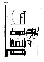
Page 5: ...cording to EN 13240 Product J tul FS 165 I 400 FL Position 6 3 pcs ca 35 mm 496 1835 1587 1258 1587 606 237 237 2 2 0 50 x y 400 R a d i a t i o n z o n e 1000 287 Min m l gulvplate measurement floorp...

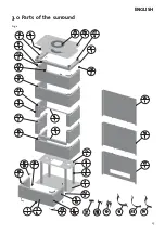
Page 6: ...25 3 0 Parts of the surround Fig 2 ENGLISH...

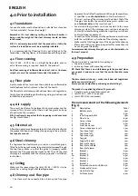
Page 7: ...acket 4 4 pcs 24 Screw countersink unb M6x16 8 pcs 25 Smoke outlet cover 2 pcs 26 Heat shield top 1 pcs 27 Distance piece 4 pcs 4 0 Prior to installation 4 1 Foundations You need to make sure the foun...

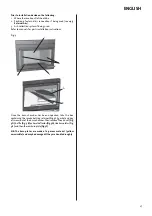
Page 8: ...tallation instructions Fig 3 F E D C A B Once the burn chamber has been unpacked take the box containing the smoke bell log retainer Fig 3 C gasket and bag of screws out of the burn chamber Then remov...

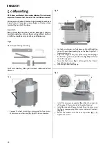
Page 9: ...s by unscrewing the two screws M8x20 mm on either side Fig 5 A of the burn chamber Fig 6 1 ca 35 mm A B C Lay the burn chamber carefully down on its back Fig 6 You can put the cardboard packaging on t...

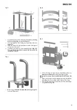
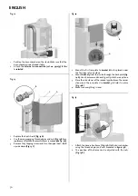
Page 10: ...installation is correct Fig 9 1 When using an External air connection cat no 341279 this has to be fitted now Fig 10 Bracket 3 Bracket 6 Bracket 1 Bracket 5 Bracket 4 Bracket 2 Bracket 2 Fig 11 A B 3...

Page 11: ...own Fig 13 C Fig 14 A B 1 Mount the first rear plate to bracket 6 that is placed under the first layer of soap stone 2 Mount bracket 3 from the inside through the back plate Fig 14 A Use a hammer and...

Page 12: ...hall rest on the attachment bracket Fig 19 B C A 1 Install the flue pipe Top smoke outlet Fig 19 A or rear smoke outlet Fig 19 B If a rear smoke outlet Remove the knockout in the rear plate Fig 19 C E...

Page 13: ...rtune to find scratches in the surface these may be polished out using a fine sandpaper If deeper scratches are present a paste made of powdered soap stone and water glass sodium silicate can be made...

Page 14: ...83...

Page 15: ...f rences d aspect de couleur et d accessoires par rapport au pr sent document Kvalitet V r kvalitetspolitikk skal gi kundene den trygghet og kvalitetsopplevelse som J tul har st tt for siden bedriften...

Reviews: