


30
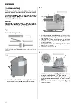
Fig. 12
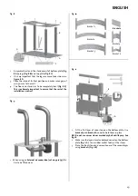
1.
Position the burn chamber on the stand. Make sure that the
burn chamber is positioned stably.
2. Attach
the
External air connection (cat. no. 341279) if this
is selected
.
Fig. 13
A
C
B
1.
Replace the heat shield
(Fig. 13 A)
.
2.
Use the accompanying threaded pins and nuts
(Fig. 13 B)
as a
replacement for M8x16mm which was removed
(see Fig. 5 A)
.
3.
Remove the 3 tapping screws and turn the upper heat shield
upside down
(Fig. 13 C).
Fig. 14
A
B
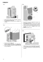
1.
Mount the first rear plate to
bracket 6
that is placed under
the first layer of soap stone.
2. Mount
bracket 3
from the inside through the back plate
(Fig.
14 A)
. Use a hammer and knock it gently into the soap stone.
3.
Place the side stones of the second layer between the corner
stones and the rear plate. Use
bracket 3
to hold it in place
(Fig. 14 B)
.
4.
Make sure everything is level.
Fig. 15
A
B
1.
Attach the decorative frame
(Fig. 15 A)
to the burn chamber
using the threaded pins and nuts mounted in
figure 13 B
.
2.
The position of the frame can be adjusted with the nuts
(Fig. 15 B).
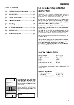
ENGLISH
Summary of Contents for FS 165-I 400 FL
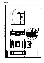
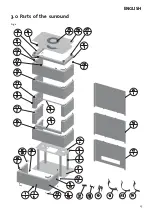
Page 6: ...25 3 0 Parts of the surround Fig 2 ENGLISH...
Page 14: ...83...


