background image

27

ENGLISH

Prior to installation, decide on the following:

1.  Where the smoke outlet should be.
2.  Position of external air connection if being used (see 

«4.5 

External Air»

).

3.  Ash collection system if being used.
Refer to manuals for parts installation instructions.

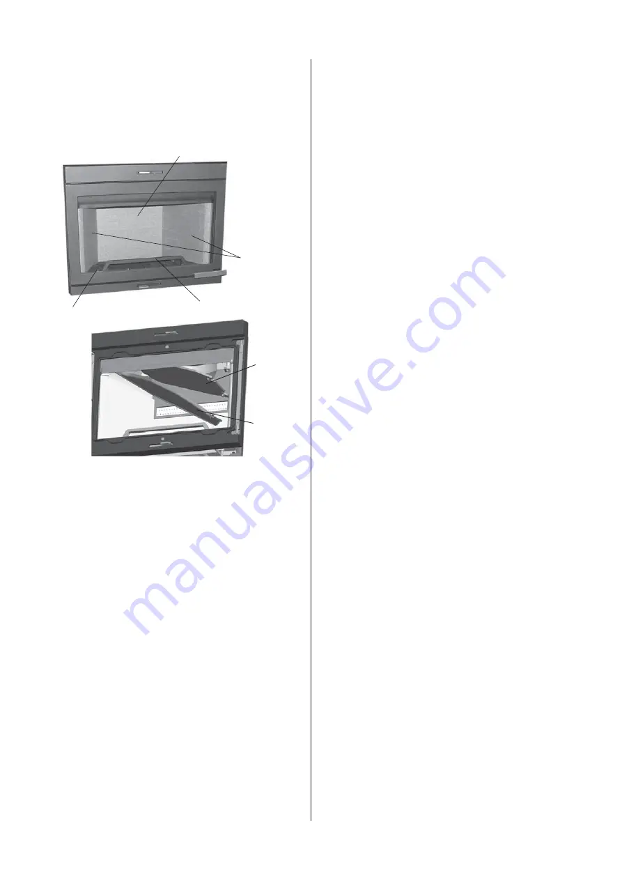
Fig. 3

F

E

D

C

A

B

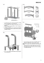
Once the burn chamber has been unpacked, take the box 
containing the smoke bell, log retainer 

(Fig. 3 C), 

gasket and bag 

of screws out of the burn chamber. Then remove the air duct 

(Fig. 

3 D)

, baffle 

(Fig. 3 B)

, exhaust deflector 

(Fig. 3 A)

, side burn plates 

(Fig. 

3 E) 

and then the rear burn plate 

(Fig. 3F)

.

NB: The burn plates are made of a porous material (yellow 
vermiculite) and may be damaged if they are handled roughly.

Summary of Contents for FS 165-I 400 FL

Page 1: ...tung f r sp tere Zwecke sorgf ltig aufzubewahren J tul FS 165 I 400 FL Manual Version P02 J tul FS 165 I 400 FL NO Monterings og bruksanvisning 4 FI Asennus ja k tt ohje 14 UK Installation and Operati...

Page 2: ...ominel varmeafgivelse Verkningsgrad vid nominell v rmeavgivning Hy tysuhde nimellisl mp teholla 74 S rskilte forholdsregler n r ovnen monteres installeres eller vedlikeholdes S rlige forholdsregler de...

Page 3: ...llation ou l entretien de l appareil x Cualquier precauci n espec fica que deba tenerse en cuenta durante el montaje instalaci n o mantenimiento del equipo de calefacci n x Precauzioni specifiche da p...

Page 4: ...burn chamber see installation manual for J tul I 400 FL Optional equipment Sidestone with hole cat no 361050 Ash solution cat no 341280 Kit for outside air connection cat no 341279 Table of contents...

Page 5: ...cording to EN 13240 Product J tul FS 165 I 400 FL Position 6 3 pcs ca 35 mm 496 1835 1587 1258 1587 606 237 237 2 2 0 50 x y 400 R a d i a t i o n z o n e 1000 287 Min m l gulvplate measurement floorp...

Page 6: ...25 3 0 Parts of the surround Fig 2 ENGLISH...

Page 7: ...acket 4 4 pcs 24 Screw countersink unb M6x16 8 pcs 25 Smoke outlet cover 2 pcs 26 Heat shield top 1 pcs 27 Distance piece 4 pcs 4 0 Prior to installation 4 1 Foundations You need to make sure the foun...

Page 8: ...tallation instructions Fig 3 F E D C A B Once the burn chamber has been unpacked take the box containing the smoke bell log retainer Fig 3 C gasket and bag of screws out of the burn chamber Then remov...

Page 9: ...s by unscrewing the two screws M8x20 mm on either side Fig 5 A of the burn chamber Fig 6 1 ca 35 mm A B C Lay the burn chamber carefully down on its back Fig 6 You can put the cardboard packaging on t...

Page 10: ...installation is correct Fig 9 1 When using an External air connection cat no 341279 this has to be fitted now Fig 10 Bracket 3 Bracket 6 Bracket 1 Bracket 5 Bracket 4 Bracket 2 Bracket 2 Fig 11 A B 3...

Page 11: ...own Fig 13 C Fig 14 A B 1 Mount the first rear plate to bracket 6 that is placed under the first layer of soap stone 2 Mount bracket 3 from the inside through the back plate Fig 14 A Use a hammer and...

Page 12: ...hall rest on the attachment bracket Fig 19 B C A 1 Install the flue pipe Top smoke outlet Fig 19 A or rear smoke outlet Fig 19 B If a rear smoke outlet Remove the knockout in the rear plate Fig 19 C E...

Page 13: ...rtune to find scratches in the surface these may be polished out using a fine sandpaper If deeper scratches are present a paste made of powdered soap stone and water glass sodium silicate can be made...

Page 14: ...83...

Page 15: ...f rences d aspect de couleur et d accessoires par rapport au pr sent document Kvalitet V r kvalitetspolitikk skal gi kundene den trygghet og kvalitetsopplevelse som J tul har st tt for siden bedriften...

Reviews: