9
A.0500.601 – Atex IM -TG G/H/MAG/SRT/08.00 EN (01/2021)
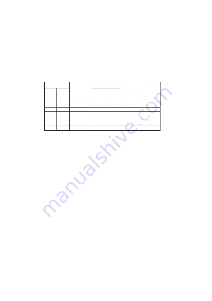
1.6.4 II 2(G)D allowable temperature TG MAG
The maximum surface temperature (T
max
) is indicated on the name plate.
T
max
is determined as the lowest temperature derived from following equations:
• T
max
= temperature limits of selected internal materials (i.e. pump selection).
• T
max
= T
5mm
- 75°C (T
5mm
“ignition temperature of a dust layer of 5 mm thickness”)
• T
max
= 2/3 x T.
CI
(T
CI
“ignition temperature of a dust cloud”).
Remark:
T
5mm
and T
CI
are to be determined by the customer/user in case of dust (D) protection.
In case the ambient temperature exceeds the range of -20°C / +40°C contact your
distributor.
Maximum surface
temperature
Pumped medium
temperature T
A
Heating medium T
A
(if any)
Separation can
temperature (L2)
Bearing bracket
temperature (L3)
T
max
T.class *)
S-jacket
T-jacket
135°C
(T4)
≤ 100°C
≤ 100°C
≤ 100°C
≤ 120°C
≤ 100°C
170°C
(T3)
≤ 130°C
≤ 130°C
≤ 130°C
≤ 150°C
≤ 100°C
200°C
(T3)
≤ 160°C
≤ 160°C
≤ 160°C
≤ 180°C
≤ 100°C
220°C
(T2)
≤ 180°C
≤ 180°C
≤ 180°C
≤ 200°C
≤ 100°C
240°C
(T2)
≤ 200°C
–
≤ 200°C
≤ 220°C
≤ 160°C **)
260°C
(T2)
≤ 215°C
–
≤ 215°C
≤ 235°C
≤ 160°C **)
280°C
(T2)
≤ 230°C
–
≤ 230°C
≤ 250°C
≤ 160°C **)
300°C
(T2)
≤ 250°C
–
≤ 250°C
≤ 270°C
≤ 160°C **)
330°C
(T1)
≤ 260°C
–
≤ 260°C
≤ 280°C
≤ 160°C **)
*) corresponding temperature class of Gas protection indicated on the nameplate between brackets
**) special bearing construction required, please contact SPX or your local distributor
1.7 Responsibility
It is the responsibility of the operator to ensure specified product temperatures are not
exceeded and to ensure regular inspections and maintenance for good operation of the
shaft seal, the bearings and the internal pump parts. If this cannot be ensured by the
operator, suitable monitoring facilities must be provided, see paragraph 1.9.
1.8 Operation
• For explosion protection it is imperative that the gear pump will not run dry. The pump
internal, including shaft seal chamber or magnetic coupling and auxiliary systems, must
be filled completely with, and lubricated by the product to be handled during operation
(including start-up, priming and shut-off).
• In case of self priming the pump must be filled with liquid and the appropriate shaft
sealing (quenched shaft seal) must be selected and controlled with regard to the
quench liquid.
• The pump must never be operated continuously with the safety relief valve opened. The
relief valve is designed as a safety device in case of over-pressure and may not be used
for flow control.
• When flow control is performed by by-passing the return liquid, the liquid must return
to the suction tank and not directly to the suction port of the pump, in which case heat
accumulation in the pump could create a dangerous situation.
• The pump must never be operated with the shutoff valves in the suction or discharge
lines closed.


