2.6
Power and Control Panels
All power and controls are contained in an IP2X cabinet
with hinged and gasket sealed outer doors.
The power section includes
A factory mounted non-fused disconnect switch with
external handle to enable connection of the unit power
supply. The disconnect switch can be used to isolate the
power for servicing.
Factory mounted compressor contactors, fuses and
over current relays to provide overload and short circuit
protection.
The control section includes
Four 7-segment LED display
Four push button switches
LED indicators for power, operation and alarm status
Customer terminal block for control inputs and liquid
flow switch connection
Microprocessor boards to provide automatic operation
and accurate temperature control.
2.7
Accessories and Options
Modbus
To integrate the unit into the building management
system. The interface permits the connection of up to 8
units using the Modbus communications protocol. Refer
to HARC Modbus data sheet (035-22384-000).
Lonworks
To integrate the unit into the building management
system. The interface permits the connection of up to 8
units using the Lon communications protocol. Refer to
HARC Lonworks data sheet (035-22383-000).
Multi Unit Sequencer - CSC-5S
Provides individual control and monitoring for up to 8
units within the air conditioning system. This allows the
units to be managed remotely from the plant room.
Compressor Circuit Breakers
Circuit breakers to replace the standard fuses for
protection against over current. The breakers provide
more precise monitoring than fuses and easy reset after
fault.
Differential Water Pressure Switch (es)
Differential pressure switches between the water inlet
and outlets to ensure liquid flow during operation.
Flow Switch (es)
Field installed flow switches to ensure liquid flow during
operation.
Glycol Cooling
Factory set-up for applications requiring water outlet
temperatures below 5°C: C ategory 1: Outlet
temperature 0 to 4°C; Category 2: Outlet temperature -1
to - 5°C and Category 3: Outlet temperature - 6 to - 10°C.
The system must have the correct percentage of glycol
added. (Refer to glycol application factors)
Discharge and/or Suction Stop Valves
Factory fitted valve(s) to allow refrigerant isolation
during servicing.
Compressor Safety Valve(s)
Factory fitted single or dual compressor safety valve(s).
2
-
2
035-21786-100 Rev. 1 (0909)
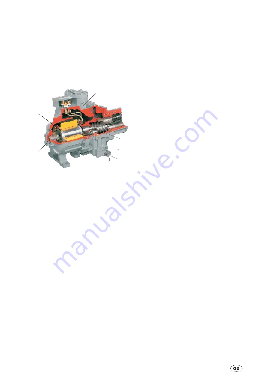
1
2
4
5
3
6
1
2-Pole Motor
2
Built-in Oil Separator
3
Twin Screw Rotors
4
Oil Sight Glass
5
Oil Heater
6
Suction Filter
Summary of Contents for York YCRE 040
Page 2: ......
Page 49: ...9 3 035 21786 100 Rev 1 0909 Suction Pressure Evaporator Sub cooling Temperatures...
Page 54: ...9 7 Clearances and Foundations 9 8 035 21786 100 Rev 1 0909...
Page 55: ...9 8 Dimensions 9 9 035 21786 100 Rev 1 0909 Model YCSE 040...
Page 56: ...9 10 035 21786 100 Rev 1 0909 Model YCSE 050...
Page 57: ...9 11 035 21786 100 Rev 1 0909 Model YCSE 060...
Page 58: ...9 12 035 21786 100 Rev 1 0909 Model YCSE 080...
Page 59: ...9 13 035 21786 100 Rev 1 0909 Model YCSE 100...
Page 60: ...9 14 035 21786 100 Rev 1 0909 Model YCRE 040...
Page 61: ...9 15 035 21786 100 Rev 1 0909 Model YCRE 050...
Page 62: ...9 16 035 21786 100 Rev 1 0909 Model YCRE 060...
Page 63: ...9 17 035 21786 100 Rev 1 0909 Model YCRE 080...
Page 64: ...9 18 035 21786 100 Rev 1 0909 Model YCRE 100...
Page 66: ...This Page Intentionally Blank 10 2 035 21786 100 Rev 1 0909...


