Johnson Controls TEC2103-1 Installation Instructions Manual Download Page 6


6

    TEC2103-1 Networked Multi-Stage Thermostat Installation Instructions 

Setup and Adjustments 

Thermostat Operation Overview 
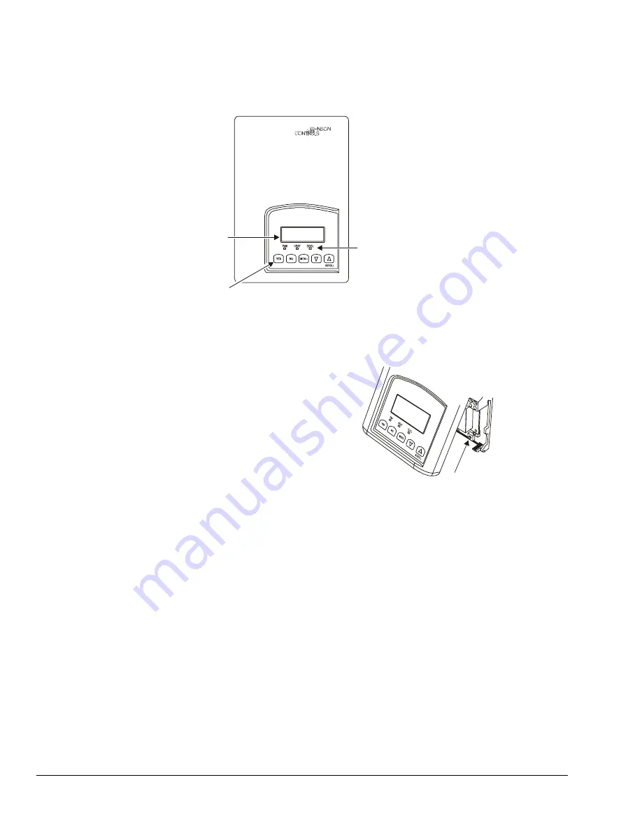
75.0ºF

Backlit, plain text, Liquid
Crystal Display (LCD)
is easy to read in any
condition.

Five keys on the TEC
make operation easy
and intuitive.

Light-Emitting Diodes (LEDs)
indicate system activity.

RoomTemp

fi

g6-

b


Figure 6: TEC2103-1 Front Cover 

Thermostat Interface Keys 

The TEC2103-1 interface consists of five keys on 
the front cover and one configuration key 
(Figure 7) that are accessed by removing the front 
cover. The functions of the keys are as follows. 
Use the: 


YES key to confirm a selection and move onto the 
next menu item 


NO key when you do not desire a parameter 
change, and to advance to the next menu item 


MENU key to access the Main User Menu or exit 
the menu 


down arrow key to scroll through menu selections 
or adjust values 


up arrow/SCROLL key to: 


stop the Status Display Menu from scrolling 


manually scroll to the next parameter on the 
menu 

 adjust 

values 

Note: 

When left unattended for 45 seconds, the 

display resumes scrolling. 

Configuration

Key

fi

g7-

b


Figure 7: Configuration Key Location 

Backlit Liquid Crystal Display (LCD) 

The TEC2103-1 uses a two-line, eight-character 
backlit display. Low level backlighting is present during 
normal operation and it brightens when any user 
interface key is pressed. The backlight returns to the 
lower level when the thermostat is left unattended for 
45 seconds. 

Light-Emitting Diodes (LEDs) 

Three LEDs are used to indicate the status of the fan, 
call for heat, or call for cooling. When: 


the fan is on, the FAN LED lights up 


heating is on, the HEAT LED lights up 


cooling is on, the COOL LED lights up 

Summary of Contents for TEC2103-1

Page 1: ...a partitioning interior wall and approximately 5 ft 1 5 m above the floor in a location of average temperature away from direct sunlight radiant heat outside walls behind doors air discharge grills st...

Page 2: ...re or malfunction of the TEC2103 1 fig1 b Figure 1 Removing the Thermostat Cover PCB Locking Tabs fig2 b Figure 2 Opening the Thermostat PCB fig3 b Figure 3 Mounting the Thermostat Base fig4 b Figure...

Page 3: ...sformer 24 VAC common from equipment transformer 24 VAC for heating stages Energizes on a call for first stage heating Energizes on a call for second stage heating Configurable digital input Configura...

Page 4: ...5 to 32 C Setback Cooling SP a g Unoccupied Cooling SP ADI 6 N2 AO CSAD 54 to 100 F 12 to 37 5 C Minimum Heat SP ADI 7 N2 AI CSAD 40 F 4 5 C Maximum Heat SP a ADI 8 N2 AO CSAD 40 to 90 F 4 5 to 32 C...

Page 5: ...selects System Mode On at the TEC keypad the TEC ends up with the System Mode On However if the Metasys system sends an override command to turn System Mode Off then the occupant selects System Mode...

Page 6: ...u item MENU key to access the Main User Menu or exit the menu down arrow key to scroll through menu selections or adjust values up arrow SCROLL key to stop the Status Display Menu from scrolling manua...

Page 7: ...he configuration key Figure 7 Exit the Installer Configuration Menu any time by pressing the MENU key and at the exit prompt pressing the YES key To pass over a parameter without changing it press the...

Page 8: ...scrolling Status Display Menu and when the message is displayed the backlight momentarily lights up Each digital input can be programmed in one of four conditions None No function is associated with...

Page 9: ...tions Enabling Frost Protection Frost pr Frost protection establishes a minimum heating setpoint of 42 F 5 5 C to prevent freezing in the zone controlled by the thermostat If enabled frost protection...

Page 10: ...erature control but could accelerate the wear of mechanical components in the equipment To set the maximum number of heating cycles per hour while in the Installer Configuration Menu 1 Answer NO to al...

Page 11: ...ess YES to store the address The display now shows the temporary occupancy time prompt See the Establishing the Temporary Occupancy Time ToccTime section for instructions Note Pressing the YES and NO...

Page 12: ...ages prompt appears in the display Press YES to enter the setting cooling stages menu 2 Using the UP DOWN arrow keys select 1 0 or 2 0 stages Press YES to store the selection The display now shows the...

Page 13: ...e Status Display Menu Override now appears for the schedule status parameter Resuming the Programmed Schedule only appears when in the Override Mode To resume the schedule while in the Main User Menu...

Page 14: ...to advance to the unoccupied heating setpoint Use the UP DOWN arrow keys to set temperature Press YES to store value and advance to next menu Press YES to change the unoccupied heating setpoint Press...

Page 15: ...ed periods even if the system mode is set to off Automatic Fan Mode auto Operates the fan only on a call for heating or cooling for both occupied and unoccupied periods This is the default setting Sma...

Page 16: ...able runs are broken Locate and correct the wiring TEC2103 1 does not come online Device type is incorrect TEC2103 1 address must be VND device type EOL jumpers on MM CVT101 or NCM are not installed I...

Page 17: ...50082 2 EMC Immunity Pending FCC Compliance This equipment has been tested and found to comply with the limits for a Class A digital device and verified to Class B pursuant to Part 15 of FCC Rules The...

Reviews: