


TEC2103-1 Networked Multi-Stage Thermostat Installation Instructions
3
2. Gently push excess wire back into the wall, plug
the wall hole with fireproof material to prevent
drafts from affecting ambient temperature
readings, and install screw terminal blocks back
onto the PCB.
3. Reattach the thermostat cover to the installed
base (top side first) and install the security screw
on the bottom.
!
CAUTION: Risk of Property Damage.
Do not apply power to the system before checking
all wiring connections. Short circuited or improperly
connected wires may result in permanent damage to
the equipment.
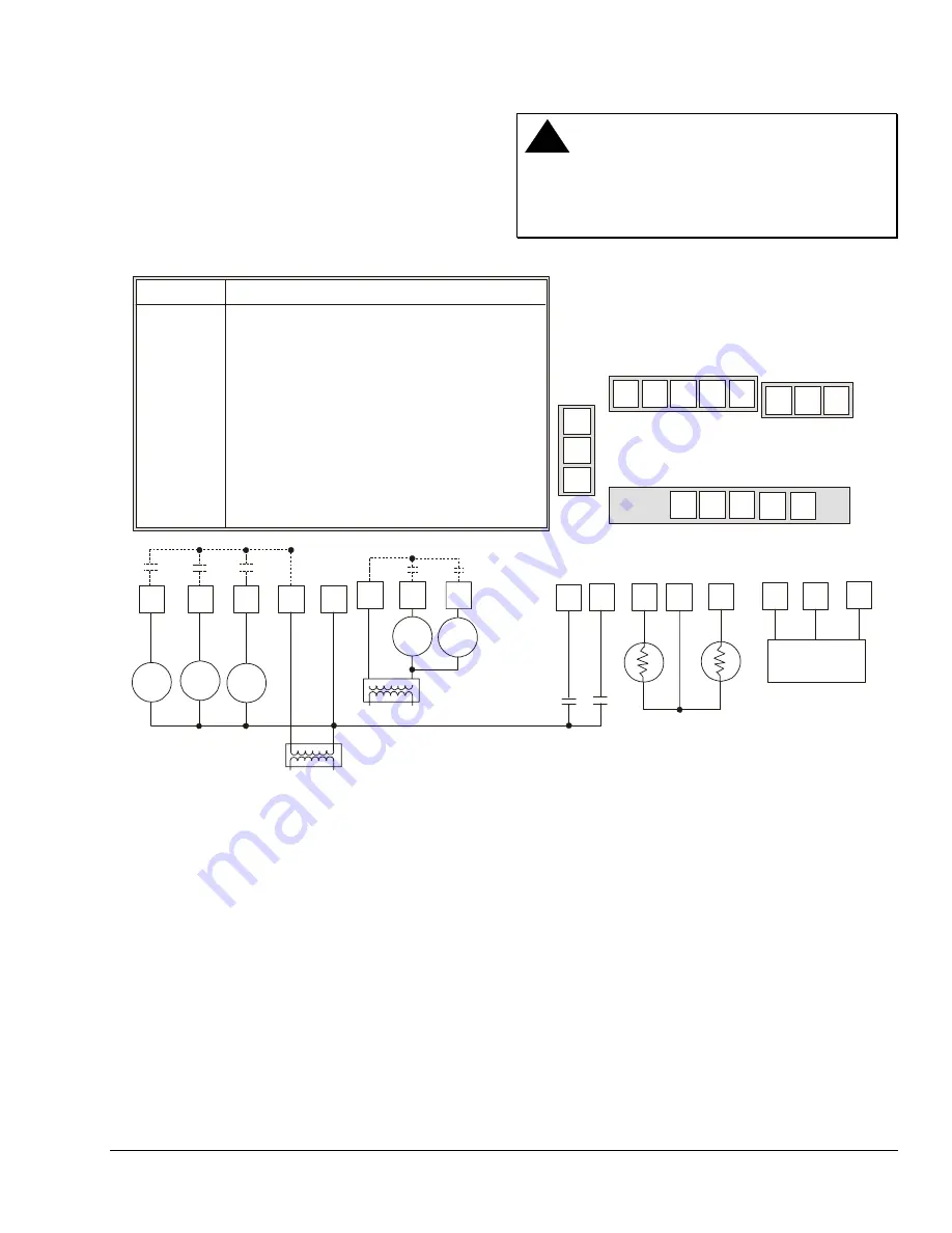
Y2
Y1
G
RC
C
RH
W1 W2
D1
D2
RS
Scom
5-pole left top connector
3-pole right top
connector
5-pole bottom connector
24 VAC
Thermostat Power
Y2
Y1
G
RC
C
If using the same power source
for the thermostat and heating
loads, install a jumper
across RC and RH.
Heat 1 Heat 2
RH
W1
W2
Fan
Cool 1
Energizes on a call for first stage cooling
Energizes on a call for second stage cooling
Energizes fan in accordance with the selected fan mode
24 VAC from equipment transformer
24 VAC (common) from equipment transformer
24 VAC for heating stages
Energizes on a call for first stage heating
Energizes on a call for second stage heating
Configurable digital input
Configurable digital input
Remote room sensor
Sensor common
Auxiliary/Outdoor air sensor
N2 Bus
Function
Y1
Y2
G
RC
C
RH
W1
W2
D1
D2
RS
Scom
OS
N2+, N2-, REF
Terminal
OS
D2
Scom
RS
D1
Remote
Room
Sensor
OS
REF
N2-
N2+
Auxiliary/Outdoor
Sensor
N2-
N2+
REF
Metasys, CPN,
NCM
Cool 2
fi
g5-
b
Figure 5: TEC2103-1 Wiring Schematic
Connecting the N2 Bus
To connect the N2 Bus:
1. Observe the polarity when connecting the N2 Bus
wires to the TEC2103-1.
Note:
An End-of-Line (EOL) is not needed on the
N2 Bus at the TEC2103-1. However, one EOL is
needed at the BAS (N30, Companion, Network
Control Module).
2. Continue this process for each TEC2103-1 using
the daisy chain wiring method.
N2 Device Mapping
When adding the TEC2103-1 to the Metasys system
(Person-Machine Interface [PMI] and Companion
system), you must define the TEC2103-1 as a Vendor
Device (VND). For the NCM, except as noted in
Table 1, Footnote c, do
not
direct map any points. Run
control of these points through the Control System
(CS) object. See the
Setting the N2 Address (N2 addr)
section to set the address for the thermostat.


