


RWH ROTARY SCREW COMPRESSOR UNITS
INSTALLATION
070.620-IOM (DEC 12)
Page 7
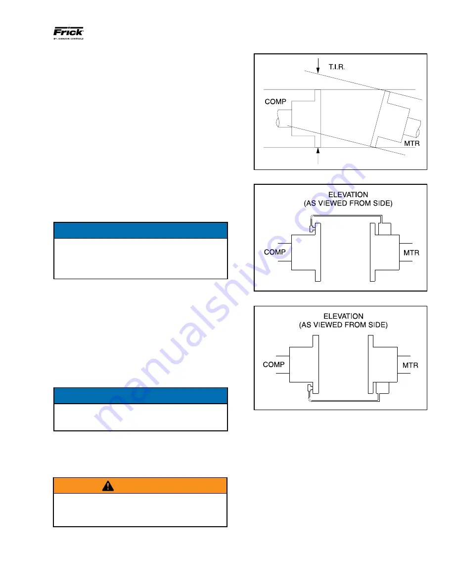
Figure 3 - Angular Misalignment
Figure 4 - Dial Indicator Attached At 12 O'clock
Figure 5 - Dial Indicator At 6 O'clock
not torque any locknuts at this time. Now pivot the unitized
flex disc until the other bushing holes in the flex disc are in
line with the bolt holes in the spacer. Install the rest of the
spacer bolts at this time. The remaining bolts for this end of
the coupling can be installed through the hub bolt holes and
flex disc bushing holes.
Install the unitized flex disc in the other end of the coupling.
The unitized flex disc, as installed, should look flat and parallel
with the mating hub and spacer flanges.
Torque the disc pack locknuts as recommended in the BP
COUPLING DATA TABLE. The bolts should be held in place
while the locknuts are torqued.
3.
Center the coupling between the shafts. Ensure that the
keys are fully engaged in their keyways.
4.
Tighten the motor and compressor shaft clamping bolts
evenly. Torque to the recommended specification in the BP
coupling data table.
5.
Torque the keyway setscrews as recommended in the BP
COUPLING DATA TABLE.
IMPORTANT
Only after the shaft clamping bolts are tightened to their
final torque can the keyway set screws be tightened. If
the keyway set screws are tightened before the shaft
clamping bolts are tightened, then the hubs can be
cocked on the shaft.
COUPLING ALIGNMENT PROCEDURE
The life of the compressor shaft seal and bearings, as well
as the life of the motor bearings, is dependent upon proper
coupling alignment. Couplings may be aligned at the factory
but realignment
MUST ALWAYS
be done on the job site after
the unit is securely mounted on its founda tion. Initial align
ment must be made prior to startup and rechecked after
a few hours of operation. Final (HOT) field alignment can
only be made when the unit is at operating tempera ture.
After final (HOT) alignment has been made and found to be
satisfac tory for approximately one week, the motor may be
dowelled to maintain align ment.
NOTICE
The recommended cold aligning of the motor is .005"
high. This cold misalignment compensates for thermal
growth when the unit is at operating temperature.
An appropriate laser instrument or set of dial indicators are to
be used to measu re the angular and parallel shaft misalign
ment. Coupling alignment is attained by alternately measur
ing angular and parallel misalignment and repositioning the
motor until the misalignment is within specified tolerances.
WARNING
ALWAYS LOCK OUT MAIN MOTOR DISCONNECT BE-
FORE TOUCHING MOTOR SHAFT. MISALIGNMENT
MUST NOT EXCEED COUPLING MANUFACTURER'S
RECOMMENDATION.
ANGULAR ALIGNMENT
1.
To check angular alignment, as shown in Figure 3, attach
dial indicator rigidly to the motor hub. Move indicator stem
so it is in contact with the outside face of compressor hub,
as shown in Figure 4.
2.
Rotate both coupling hubs several revolutions until they
seek their normal axial positions.
Check the dial indicator to be sure that the indicator stem is
slightly loaded so as to allow movement in both direc tions.
3.
Set the dial indicator at zero when viewed at the 12 o’clock
position, as shown in Figure 4.
4.
Rotate both coupling hubs together 180° (6 o’clock posi
tion), as shown in Figure 5. At this position the dial indicator
will show TOTAL angular misalignment.