


RWH ROTARY SCREW COMPRESSOR UNITS
OPERATION
070.620-IOM (DEC 12)
Page 20
• Place the leads of a calibrated, quality meter to ter
minal one (positive) and terminal two (negative). Set
the meter to read mA DC and power up the panel.
• Set operating session to session [2] and go to the
screen shown in Figure 24 by pressing
[Menu]
>
[Cali-
bration]
>
[Analog Outputs]
>
[Output Calibration]
.
• Press #1 on the keypad to drive the output to the
low end. Using numbers 4, 7 and 0 on the keypad
to increase and decrease the output and change the
“Delta For Changing Output Percentage” setpoint, set
the output to 4mA.
• If the read value is less than the objective of 4 or 20mA
use 7 on the keypad, increase the output by the Delta.
If the read value is more than the objective, use 4 to
decrease the value by the Delta.
• Use the 0 key to change the Delta from 10 to 1, .10
or .01% to tune the output to the objective of 4 or
20mA.
• Press #3 on the keypad to set the output to the high
end and repeat the process in the preceding steps to
set the output to 20mA.
• Power down the panel, remove the meter and recon
nect the control wires for the EZCool LIOC valve as
they were removed to terminals 1 & 2 of the P11A
terminal strip of analog board #1.
Description of Proportional Band and Gain setpoints:
• Proportional Band
– This setpoint determines the size
of a region either above or below the Control Setpoint.
Within this region the Proportional component of the
PID Output value is the number between 0% and 100%
that directly corresponds to the difference between
the Control Input (Actual) and the Control Setpoint
(Setpoint). Outside of this region the Proportional
component is either 100% or 0%. If the PID Action
is Forward, the Proportional Band extends above the
Control Setpoint. If the PID Action is Reverse, the
Proportional Band extends below the Control Setpoint.
• Proportional Gain
This value is calculated from the
Proportional Band setpoint and is the same value that
was entered as a Proportional Gain setpoint in the
Quantum. The control setpoint will not be achieved
with proportional control only. Integral control is
needed to further correct the control input to achieve
the setpoint.
• Integral Gain
This setpoint controls the influence the
Integral component exerts on the PID Output value.
The Integral component works to push the Control
Input toward the Control Setpoint by tracking the
difference between the Control Input and the Control
Setpoint over time.
• Derivative Gain
This setpoint controls the influence
the Derivative component exerts on the PID Output
value. The Derivative component reacts to rapid
changes in the value of the Control Input by predicting
the direction the Control Input is traveling and then
turning it back toward the Control Setpoint.
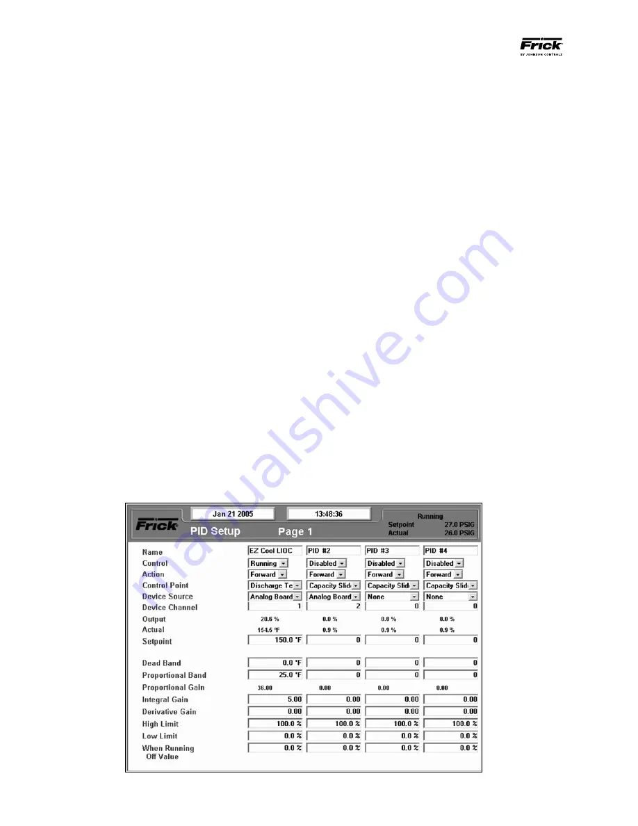
Example of Proportional Only Control:
Control Input:
Discharge Temperature
Control Setpoint:
150°F
Dead Band:
0°F
Proportional Band: 25
Action:
Forward
NOTES:
1. Set the “Liquid Slugging” Alarm and Shutdown setpoints
to 90 to prevent nuisance shutdowns during the tuning
process. Be sure to return these setpoints to their original
values when finished.
2. While the discharge temperature will be the Control Point,
it reacts quickly to adjustments. Be sure to allow an adjust
ment to the proportional band or integral gain setpoints the
opportunity to counter and correct the control input (dis
charge temperature) before making additional adjustments.
3. Tune the output by making small adjustments of 15 to
the Proportional Band and .1.5 of the Integral Gain setpoints.
Adjust only one at a time, allowing each adjustment time to
settle out.
Figure 25 - PID Setup