


RWH ROTARY SCREW COMPRESSOR UNITS
INSTALLATION
070.620-IOM (DEC 12)
Page 12
ECONOMIZER - HIGH STAGE (OPTIONAL)
The economizer option provides an increase in system ca
pacity and efficiency by cooling liquid from the condenser
through a heat exchanger or flash tank before it goes to the
evapora tor. The cooling is provided by flashing liquid in the
economizer cooler to an intermediate pressure level. The
intermediate pressure is provided by a port located part way
down the compres sion process on the screw compressor.
As the screw compressor unloads, the economizer port will
drop in pressure level, eventually being fully open to suc
tion. Because of this, an output from the microproces sor is
generally used to turn off the supply of flashing liquid on a
subcooler when the capacity falls below approximately 60%
70% capacity (85%90% slide valve position). This is done
because the compressor will be more efficient operating at
a higher slide valve position with the economizer turned off,
than it will at a low slide valve position with the economizer
turned on. Please note however that subcooler can be used
at low compressor capaciti es in cases where efficien cy is not
as important as assuring that the liquid supply is subcooled.
In such cases, the economi zer liquid control valve can be left
open whenever the com pressor is running.
Due to the tendency of the port pressure to fall with de creasing
compressor capacity, a backpressure regulator valve (BPR) is
generally required on a flash economizer system (Figure 14) in
order to maintain some preset pressure dif ference between
the subcooled liquid in the flash vessel and the evaporato rs.
If the backpressure regulator valve is not used on a flash
economizer, it is possible that no pressure difference will exist
to drive liquid from the flash vessel to the evaporators, since
the flash vessel pressure will approach suction pressure at a
decreased slide valve position. In cases where wide swings
in pressure are anticipated in the flash econo mizer vessel, it
may be necessary to add an outlet pressure regulator to the
flash vessel outlet to avoid overpressurizing the economizer
port, which could result in motor overload. Example: A sys
tem feeding liquid to the flash vessel in batches.
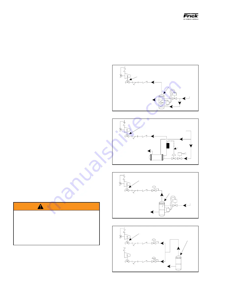
The recommended economizer systems are shown in Figures
1316. Notice that in all systems there should be a strainer
(STR) and a check valve (VCK) between the economizer ves
sel and the economizer port on the compressor. The strainer
prevents dirt from passing into the compressor and the check
valve prevents oil from flowing from the compressor unit to
the econo mizer vessel during shutdown.
WARNING
Other than the isolation valve needed for strainer clean-
ing, it is essential that the strainer be the last device
in the economizer line before the compres sor. Also,
piston-type check valves are required for installation
in the economizer line, as opposed to disc-type check
valves. The latter are more prone to gas-pulsation-
induced failure. The isolation and check val ves and
strainer should be located as closely as possible to the
compressor, preferably within a few feet.
For refrigeration plants employing multiple compressors on
a common economizing vessel, regardless of economizer
type, each compressor must have a backpressure regulat
ing valve in order to balance the economizer load, or gas
flow, between compressors. The problem of balancing load
becomes most important when one or more compressors
run at partial load, exposing the economizer port to suction
pressure. In the case of a flash vessel, there is no need for
the redundancy of a backpressure regulating valve on the
vessel and each of the multiple compressors. Omit the BPR
valve on the flash economizer vessel and use one on each
compressor, as shown in Figure 16. It is also recommended
that the backpressure regulating valves, used on economizer
lines, should be specified with electric shutoff option. The
electric shutoff feature is necessary to prevent flow from the
common economizer vessel to the suction side of a stopped
compressor, through the suction check valve bypass line, if
the other compressors and the common economizer vessel
Figure 14 - Direct Expansion Economizer System
Figure 13 - Shell and Coil Economizer System
Figure 16 - Multiple Compressor Economizer System
Figure 15 - Flash Economizer System
HIGH
PRESSURE
LIQUID
INTERMEDIATE PRESSURE
GAS TO COMPRESSOR
SUCTION
STR
VCK
SUBCOOLED
HIGH PRESSURE
LIQUID TO
EVAPORATOR
ECONOMIZER
COOLER
ECON1
HV-2
HIGH
PRESSURE
LIQUID
INTERMEDIATE PRESSURE
GAS TO COMPRESSOR
SUCTION
STR
VCK
SUBCOOLED
HIGH PRESSURE
LIQUID TO
EVAPORATOR
ECONOMIZER
COOLER
WIRING
ECON2
HV-2
HIGH
PRESSURE
LIQUID
INTERMEDIATE PRESSURE
GAS TO COMPRESSOR
SUCTION
STR
VCK
CONTROLLED
PRESSURE
SATURATED LIQUID
TO EVAPORATOR
ECONOMIZER
VESSEL
BPR
ECON3
HV-2
INTERMEDIATE PRESSURE
GAS TO COMPRESSOR
SUCTION
STR
VCK
BPR
CONTROLLED PRESSURE
SATURATED LIQUID TO EVAPORATOR
ECONOMIZER
VESSEL
ECON4
HV-2