background image

CD-W00-x0-2 Series Wall Mount CO

2

 and Temperature Transmitters Installation Instructions

3

Note:

When you bring the cable through the wall, seal 

the cable opening. If left unsealed, the hole allows air 
from outside the room into the transmitter and affects 
the measurement readings. For example, fresh 
concrete binds CO

2

 and may cause low readings, 

especially in new buildings.

Connecting the Cable to the Mounting Base

Connect the wires from the cable to the screw 
terminals on the mounting base. The terminal 
assignments are marked next to the screw terminals. 
Maximum wire size is 2 mm

2

 (AWG 14).

1. Strip 1/4 in. (6.35 mm) of insulation from the ends 

of the power and output signal wires.

Note:

To prevent a short circuit from occurring, make 

sure that the wires are stripped to the correct length 
and fully inserted into the terminal blocks. If using 
shielded cable, ensure that the shield is protected from 
contact with components on the top or bottom side of 
the printed circuit board. Failure to follow proper wiring 
procedures may cause the transmitter to fail.

2. Connect the wires to the mounting base screw 

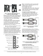
terminals as shown in Figure 4.

Note:

The transmitter is capable of generating both 

voltage and current output. Each output has its own 
individual positive screw terminal.

Power Supply Requirements

The transmitter requires a 24 VAC/VDC, Class 2 power 
supply. Although the power input includes a halfwave 
rectifier, we recommend using a DC supply to avoid 
excessive current peaks.

Connections to a 24 VAC Power Supply

Connecting more than one transmitter to a single 
24 VAC transformer forms a common loop and 
increases the risk of a short circuit. We recommend 
that you use a separate floating supply for each 
transmitter (see Figure 5).

If several transmitters share a common transformer, 
always connect the transmitter common (-) to the same 
side of the transformer to maintain the polarity. A 
shared common line at the controller may cause a 
short circuit if the phase is not the same (Figure 6).

Completing the Installation

Install the cover on the mounting base:

1. Slide the bottom of the cover onto the tabs at the 

bottom of the mounting base.

2. Tilt the top of the cover toward the mounting base.

Figure 3: Route the Cable From Behind (Left) 

and Mount the Wall Plate (Right)

NO

  CABLES

UP

Figure 4: Screw Terminals

+

-

+CO2
4...20mA

+CO2
0...10 V

-CO2

VS

~

t+

Signal Out 4 to 20 mA (+)

Signal Out 0 to 10 V (+)

Signal Common (-)

Power Supply Common (-)

Power Supply 24 VAC/DC (+)

Temperature Sensor

Temperature Sensor Common

F

IG

:C

O

2_w

rn

g

Figure 5: Connecting Separate AC Supplies 

(Recommended)

Supply

voltage

24 VAC

24V

mA or V

Common

Signal

output

CONTROLLER

CO2 Transmitter/

Module

CO2 Transmitter/

Module

24V

mA or V

Common

Supply

voltage

24 VAC

Signal

output

F

IG

:c

o

n

n

_

se

p

ac

Figure 6: Connecting One AC Supply to Several 

Transmitters (Not Recommended)

Supply

voltage

24 VAC

24V

mA or VA

Common

Signal

output

CONTROLLER

CO2 Transmitter/

Module

CO2 Transmitter/

Module

24V

mA or VA

Common

Supply

voltage

Signal

output

F

IG

:c

o

n

n

_

sn

g

se

v

SHARED

COMMON

LINE

Summary of Contents for CD-W00-00-2

Page 1: ... injury or property damage to the controlled equipment or other property additional precautions must be designed into the control system Incorporate and maintain other devices such as supervisory or alarm systems or safety or limit controls intended to warn of or protect against failure or malfunction of the transmitter IMPORTANT Le CD W00 x0 2 Series Wall Mount CO2 and Temperature Transmitters es...

Page 2: ...ircuited or improperly connected wires may result in permanent damage to the equipment MISE EN GARDE Risque de dégâts matériels Ne pas mettre le système sous tension avant d avoir vérifié tous les raccords de câblage Des fils formant un court circuit ou connectés de façon incorrecte risquent d endommager irrémédiablement l équipement CAUTION Risk of Property Damage Do not run low voltage cable in ...

Page 3: ...ve rectifier we recommend using a DC supply to avoid excessive current peaks Connections to a 24 VAC Power Supply Connecting more than one transmitter to a single 24 VAC transformer forms a common loop and increases the risk of a short circuit We recommend that you use a separate floating supply for each transmitter see Figure 5 If several transmitters share a common transformer always connect the...

Page 4: ...n System BAS controller s analog input AI high range to compensate for sensor placement at other than the standard calibration altitude To do this reset the 2 000 ppm value using the controller s compensation factor CF shown in Figure 7 or Figure 8 Calculate the corrected value Corrected Value CF x 2 000 For example if the sensor is situated at an altitude of 3 000 ft 914 4 m above sea level the C...

Page 5: ...t 21 C Operating Temperature Range 32 to 122 F 0 to 50 C Storage Temperature Range 40 to 158 F 40 to 70 C Operating Humidity Range 0 to 95 RH noncondensing 86 F 30 C maximum dew point Transmitter CO2 Output Signal 4 to 20 mA and 0 to 10 VDC Maximum Output Current 21 mA Maximum Output Voltage 11 V Resolution of Analog Outputs 0 3 ppm CO2 Recommended External Load Minimum 1 000 ohms load resistance ...

Page 6: ...ht Dieser Sensor Transmitter kann nur wandmontiert eingesetzt werden Der elektrische Anschluß ist nach den örtlichen Vorschriften durch autorisiertes Personal durchzuführen Versorgungsspannung und Niederspannung sind getrennt zuzuführen Bei Verwendung von flexiblen Leitungen sind Kabelschuhe zu verwenden Überprüfen Sie alle Kabelverbindungen bevor Sie den Antrieb einschalten Der Kontakt mit Kompon...

Page 7: ...rollera alla kabelförbindelser innan du tillkopplar ställdonet Kontakt med komponenter med farlig spänning kan ge elektriska stötar som kan orsaka allvarliga eller livshotande personskador Kortslutna eller felaktigt anslutna kablar kan resultera i varaktiga skador på utrustningen Om innehållet i den här bruksanvisningen inte efterföljs kan det leda till skada på person eller utrustning Om anslutni...

Page 8: ...кранирован Экран следует заземлять в одной точке на стороне контроллера Сохраните этот документ Portuguese Certifique se que a fonte de alimentação é compatível com a fonte de alimentação especificada na secção de Especificação Técnica Este sensor transmissor foi projetado para montagem somente em parede Toda a fiação eletrica devera ser realizadas segundo a disposicão locais e apenas por pessoal ...

Reviews: