JK
microsystems
Flashlite 186
User’s Manual
8
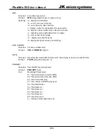
The following code illustrates the use of
inportb()
and
outportb()
.
unsigned char port;
port = inportb(PORT_DIR);
/* get value of dir. reg */
port |= PORT_DIR_MASK;
/* set dir. bit for input */
outportb(PORT_DIR, port);
/* write value to dir. reg */
printf("PORT: 0x%X\n", (int)inportb(PORT));
/* read & print port value */
Asynchronous Serial Ports
The Flashlite has 2 serial ports, Serial 0 and Serial 1. Both ports are internal to the R8822. These
UARTs are not compatible with the 16450 UARTs on a PC. The maximum data rate is 115k
Baud at RS-232 levels.
Serial 0 is wired as Data Terminal Equipment (DTE) for connection to a peripheral such as a
modem. This port is jumper configurable to be either RS-232, TTL level RS-232 (2 wire) or
half-duplex RS-485. When configured to use RS-232 levels, this is port implements the
handshaking RTS, CTS, and DCD control lines.
Serial 1 is wired as Data Communications Equipment (DCE) for direct connection to a computer
or terminal. This port is configured as a 3 wire RS-232 port implementing RxD and TxD.
The Serial Debug/Console port does not make use of a hardware UART. It is intended for
console and debugging purposes only and should not be used in a design requiring high data
throughput. Its design generates an interrupt for each bit of serial data, and puts a large load on
the processor when data is being received.
Driver functions for Serial 0 and Serial 1 are available in the
CSPD.COM
TSR and related
.LIB
and
.H
files located in the
Flashlite186/drivers
subdirectory on the utilities CD.
Please refer to the RDC R8822 User’s Manual for specific information on the serial ports and
their configuration.
RS-485 Configuration
The Serial 0 port of the Flashlite can be configured and used for RS-485 communications. To
configure Serial 0 as RS-485, move the jumper on JP2 to the 1-2 location. RS-485 signals are
present on pins 1 and 2 of J5. The RTS line on Serial 0 is used to control the RS-485 transmitter.
Library functions are available for use with RS-485 in the supplied driver.
The RS-485 driver is internally looped back. Characters transmitted will appear in the UART
receiver. This condition is inherit with the RS-485 implementation and may present user
applications implications.
Hardware
Summary of Contents for Flashlite 186
Page 1: ...Flashlite 186 User s Manual ...
Page 2: ......
Page 6: ...JKmicrosystems Flashlite 186 User s Manual iv ...
Page 17: ......
Page 27: ...21 Flashlite 186 User s Manual JKmicrosystems Contact Information ...


