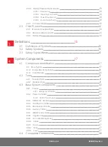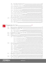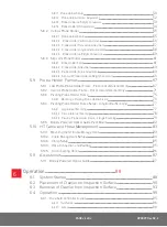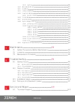
PAGE vii of ix
DP0029 Rev 02.2
5.8.1.1 Probe Holder Setup
50
5.8.1.2 Probe Holder Vertical Adjustment
52
5.8.1.3 Probe Holder Left/Right Conversion
53
5.8.1.4 Probe Holder 90° Adjustment
54
5.8.2. Vertical Probe Holder
55
5.8.2.1 Probe Holder Setup
55
5.8.2.2 Probe Holder Vertical Adjustment
56
5.8.2.3 Probe Holder Transverse Adjustment
57
5.8.2.4 Probe Holder Longitudinal Adjustment
58
5.8.2.5 Probe Holder Left/Right Conversion
59
5.8.3. Slip Joint Probe Holder
61
5.8.3.1 Probe Holder Setup
61
5.8.3.2 Probe Holder Adjustment
63
5.8.3.3 Probe Holder Force Adjustment
63
5.8.3.4 Slip Joint Probe Holder Left/Right Conversion
65
5.9. Probe Holder Frames
67
5.9.1. Low Profile Probe Holder Frame - Flat or Circumferential Only
67
5.9.2. Vertical Probe Holder Frame - Flat or Circumferential Only
71
5.9.3. Pivoting Probe Holder Frame
75
5.9.3.1 Mounting a Pivoting Probe Holder Frame
76
5.9.4. Pivoting Probe Holder Frame Setup - Longitudinal Scanning
77
5.9.4.1 Longitudinal Scanning
77
5.9.4.2 Circumferential Scanning
78
5.9.4.3 Pivoting Probe Holder Frame - Flange Scanning
79
5.9.5. Battery Powered Optical Guide Pivot Mount
82
5.10. HT Cable and Hose Management
83
5.10.1. Mounting the HT Cable Management
83
5.10.2. Cable Management Setup
84
5.10.3. Clamp Setup
85
5.10.4. Hose Connection and Routing
85
5.10.5. Disconnecting Hoses
86
5.11. Accessories
87
5.11.1. Battery Powered Optical Guide
87
Chapter
6
Operation
88
6.1. System Startup
88
6.2. Placement of Crawler on Inspection Surface
90
6.3. Removal of Crawler from Inspection Surface
93
6.4. Operation
95
6.4.1. Handheld Controller Layout
95
6.4.1.1 Touchscreen
96
6.4.1.2 D-pad
96


