background image

9

Operations Manual

2. Introduction

FishSAFE is a hands free device which warns a fishing vessel skipper of nearby

surface and seabed obstructions that may be a hazard and may become caught in

fishing gear. FishSAFE uses a combination of visible and audible warnings to indicate

the level of risk. FishSAFE provides the skipper with an appreciation of potential

hazards, allowing the appropriate action to be taken on-board to minimise risk.

There are two types of risk areas (hazards) which are capable of triggering an

alarm. These are Safety Zones and Hazard Areas.

1. Safety Zones. In the UK, Under the Petroleum Act 1987 the Secretary

of State may, by Order, establish a 500m Safety Zone around a sub-

sea installation within designated waters. Under the same Act all oil

and gas installations which project above the sea surface at any state

of the tide are automatically protected by a Safety Zone. (Merchant

Shipping Notice NO. M.1290, Department of Transport, Marine

Directorate, London, September 1987). Both of these types are shown

on the FishSAFE unit as Safety Zones.

2. Hazard Areas. In the UK, a hazard area is not designated by Order

and indicates a hazardous region around an extended sub-sea object

such as a sub-sea pipeline.

The alarm behaviour of the unit regarding a Safety Zone and a Hazard Area is

similar but there are differences in terms of the Cancel Alarm time-out and the

behaviour of the Audible Alarms. See Par. 7.2 and 7.4.

NOTE

The exact behaviour of the unit is determined by the FishSAFE database. This

manual describes the operation of the FishSAFE unit when used in conjunction

with the database dated September 2009.

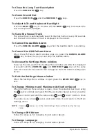
Summary of Contents for fishsafe

Page 1: ......

Page 2: ...3 Operations Manual Reducing Risk from Surface and Subsea Obstructions Operations Manual code FishSAFE A171109e...

Page 3: ...C Services Ltd a not for profit company whose members are The Scottish Fishermen s Federation The National Federation of Fishermen s Organisations and Oil Gas UK The FishSAFE project is supported by g...

Page 4: ...iew 19 5 1 KEY FUNCTIONS OVERVIEW 19 5 2 QUICKSTART GUIDE 19 5 3 SCREEN LAYOUT 21 6 FishSAFE Normal Operation 23 6 1 POWER UP 23 6 2 MOVING AROUND THE SCREEN 23 6 3 QUICK INFO WINDOW 23 6 4 ZOOMING 24...

Page 5: ...6 Operations Manual...

Page 6: ...d use government charts and prudent navigation practices To operate a FishSAFE unit you must first accept 1 the FishSAFE Terms and Conditions of Supply Maintenance and Use the FS unit terms and condit...

Page 7: ...8 Operations Manual...

Page 8: ...thin designated waters Under the same Act all oil and gas installations which project above the sea surface at any state of the tide are automatically protected by a Safety Zone Merchant Shipping Noti...

Page 9: ...10 Operations Manual...

Page 10: ...1 Operations Manual 3 Parts Checklist Your FishSAFE box should contain the following items FishSAFE unit Mounting Bracket Combined Power and NMEA lead Flush Mount Kit Fuse and Holder Operations Manual...

Page 11: ...12 Operations Manual...

Page 12: ...nd Flush Mounting The figures below show examples of Flush Mounting see Fig 4 1 and Bracket Mounting see Fig 4 1a n 4 HOLES 356mm 14 264mm 10 4 10mm 0 4 R13mm 0 5 234 5mm 9 2 340mm 13 4 337mm 13 3 CUT...

Page 13: ...o the FishSAFE unit 10 32v DC Power External GPS NMEA Input Output not used SMART GPS SENSOR Optional Accessory Fig 4 3 FishSAFE Connections 4 4 CABLE WIRING DIAGRAM The FishSAFE unit has two connecto...

Page 14: ...antenna if a position is not received from the 3rd party GPS for 30 seconds Setting of these two ports will be completely automatic and they support normal NMEA 0183 connections i e 4800N 8 1 1 POWER...

Page 15: ...hen the above screen is displayed the ZOOM IN and the ZOOM OUT keys can be held down for 5 seconds to give access to the System Settings NOTE Pressing takes you to the main Settings Menu without savin...

Page 16: ...the Datum reference used by the GPS receiver connected to the unit so that the unit converts the position received from the GPS to the Map Datum currently selected in the menu in order to match the po...

Page 17: ...18 Operations Manual...

Page 18: ...tance of Disclaimer After reading the Disclaimer press the ZOOM IN key to confirm To Power Down the Unit Press and hold the POWER key for 5 seconds To Show Hide the Cursor Move the cursor pad and the...

Page 19: ...dow Power up the unit wait for the Settings Menu window and while it is displayed press and hold the ZOOM IN and ZOOM OUT keys at the same time for 4 seconds The selector bar will appear Now the desir...

Page 20: ...key for 1 second at the same time The screen shot is captured and saved to SD Card in bmp format To Save the Vessel Track on the SD Card Insert the SD Card press the CANCEL ALARM key and the DIM key...

Page 21: ...s On Screen Object Description Range and Bearing Time to Hazard Warning Message Fig 5 3a Screen Layout II Speed Over Ground Course Over Ground Vessel Position GPS Time UTC Outer Range and Range Ring G...

Page 22: ...vides the cursor position distance and bearing from the vessel As soon as the cursor time out occurs and the cursor disappears this window will disappear Fig 6 2 Displaying vessel 6 3 QUICK INFO WINDO...

Page 23: ...d range rings except at the 0 5NM range where there will only be four As the user Zooms In or Out the chart scale changes and the displayed range value changes in the lower right hand corner There are...

Page 24: ...th being based upon the vessel position Circle radius is variable set by trawl length setting Course Indicator length fixed at 5 minutes Arc length fixed at 3NM Fig 6 6 The Keyhole When the Forward Se...

Page 25: ...26 Operations Manual...

Page 26: ...rd Status Bar is displayed along the top of the screen as shown below see Fig 7 1a Fig 7 1a The display screen with the Hazard Status Bar Whenever the Hazard Status Bar is displayed there will always...

Page 27: ...Speed where distance is measured from the vessel to the closest edge of the safety zone or hazard boundary which is within the For ward Sector The time is only displayed when edge of the safety zone o...

Page 28: ...side Hazard Area Rapid Beeping 1 sec ON 1 sec OFF Red Inside Safety Zone Rapid Beeping 1 sec ON 1 sec OFF All Audible Alarms can be cancelled by pressing the CANCEL ALARM key which silences the Alarm...

Page 29: ...FE will display the following Alarm window and sound a Slow Double Beep Audible Alarm Fig 7 4 1 GPS Failure Alarm window Pressing the CANCEL ALARM key cancels the GPS Failure Alarm and the Time out on...

Page 30: ...here Fig 8 1 Startup screen 6 Hit the ZOOM IN key to close the window 7 When the system has rebooted you should remove the SD Card 8 1 1 Internet Download The SD Card can be updated via Internet Downl...

Page 31: ...dow 7 When the system has rebooted you should remove the SD Card NOTE It is most important that the update of Operating System is not interrupted Do not switch the unit Off or interrupt the units powe...

Page 32: ...ase contact Jeppesen Marine Light Marine Division Customer Services OEM Solutions ph 39 0585 794739 fax 39 0585 794755 EU customersupport jeppesen com Jeppesen Italia s r l Centro Direzionale Olidor V...

Page 33: ...34 Operations Manual...

Page 34: ...es Voltage 10 32v DC Power Consumption 1 5A max 12V DC NMEA 0183 Version 2 xxGGA xxGLL xxRMC sentences at 4800 baud Mounting Flush Panel or Bracket Mounting see previ ous Par 4 1 Warning Indicators 4...

Page 35: ...36 Operations Manual...

Page 36: ...ns 14 FishSAFE Normal Operation 23 FishSAFE unit 11 33 Flush Mount Kit 11 Flush Mounting 13 Flush Panel 35 Forward Sector 24 Fuse and Holder 11 G GGA 35 GLL 35 GPS 23 GPS Antenna 14 15 GPS Antenna con...

Page 37: ...t Text Description 23 show hide cursor 19 Simulation Mode 21 Simulator Menu 21 Siren test 16 Special Startup 35 splash screen 16 23 Startup screen 31 STD 23 System Setting 16 System Test menu 16 SYSTE...

Page 38: ......

Page 39: ......

Reviews: