500 795/Rev D/07-14
Page 34
2.
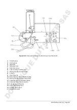
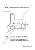
FUSES
Two fuses are fitted to the instrument.
FS1
is the primary fuse provided
to protect the instrument and any accessories connected to the
power
out
sockets.
FS2
is to protect the electronic circuitry in the PFP7. Both
FS1 and FS2 should be of an anti-surge type.
3.
POWER IN
A three pin receptacle for the AC mains supply.
4.
POWER OUT
Two three pin sockets for flame photometer accessories such as a
compressor. The power from these sockets is controlled by the
instrument
power
switch on the front panel.
5.
RECORDER
Two 4mm sockets which will provide an analogue signal of
approximately 1 volt when the readout is 1000 digits or 100.0, 10.00,
1.000.
6.
FUEL GAS
1/4" connector for fuel tubing.
IMPORTANT: Fuel supply must be regulated to 10-15 inches water
gauge (0.36-0.54psi or 0.025-0.38kg/cm
2
. See section 2.1.2 for
information on different fuel types.
7.
AIR
5/16" connector for air tubing.
IMPORTANT: Air pressure on the inlet to the instrument must not
exceed 30psi (2kg/cm
2
). See section 2.1.3.
4.2
Operation Flame Ignition and Optimisation
1. Ensure that the drain trap is pushed fully down on its clip. Ensure that the drain trap
solution in it and that no air locks are present. If necessary, purge by adding
water and allowing the surplus to run
2. Close the
fuel
valve by turning fully clockwise. To avoid damaging the valve, it
not
be
3. Turn the
fuel
valve the required number of turns anti-clockwise depending on the
being
Fuel Number of
Propane
Butane
Natural gas Fully
L.P.G.
4. Turn on the fuel supply at source i.e.
5. Switch on electrical power by depressing the
power
switch. If the air compressor is
powered separately, switch on the air compressor. Ensure that air is present
listening for the hissing created as it passes through the
DOMINIQUE DUTSCHER SAS

