background image

8

High Altitude Conversions

IMPORTANT:

 You must convert LP gas with LP gas high altitude 

kit Part Number W10686630 or Natural gas with Natural gas 

high altitude kit Part Number W10686629. If you need to convert 

LP gas to Natural gas high altitude or Natural gas to LP gas 

high altitude, you must convert the pressure regulator. For this, 

follow steps 1-3 of the necessary conversion.

Natural Gas Orifice Spud Chart for High Altitude Conversion:

See chart in the “Natural Gas High Altitude Conversion Kit.”

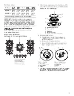
Burner locations

30" (76.2 cm) and 36" (91.4 cm) Models

5. 

Remove all burner caps and burner bases. Be sure to keep 

the cap and base for each burner together. This will assure 

that the cap and base are reinstalled on the proper burner.

6. 

To convert burners:


Insert 7.0 mm nut driver down onto the gas orifice spud 

and remove by turning it counterclockwise and lifting out.


Set gas orifice spud aside.


Replace with correct Natural gas orifice spud. 

See the Natural Gas Orifice Spud Chart.

A

B

C

A

C

B

D

Standard and simmer burners

A.  Igniter electrode
B.  Orifice holder
C.  Orifice spud

Dual flame burner

A.  Igniter electrode
B.  Orifice holder
C.  Orifice spud
D.  Orifice simmer

7. 

Place LP gas orifice spuds in plastic parts bag for future 

use and keep with package containing literature.

8. 

Replace burner bases and burner caps.

IMPORTANT:

 Be sure that the electrode aligns with 

the notch or hole in the burner base. The igniter 

electrode is ceramic and could break during installation 

of the burner base.

9. 

Open shutoff valve in the gas supply line. The valve 

is open when the handle is parallel to the gas pipe.

10. 

Once you have completed converting all of the cooktop 

burners, test the cooktop for leaks by brushing on an 

approved noncorrosive leak-detection solution. If bubbles 

appear, a leak is indicated. Correct any leaks found.

11. 

Plug in cooktop or reconnect power.

12. 

Adjust valve according to “Low Flame Height 

Adjustment” section.

Lo

Hi

Lo

Hi

Lo

Hi

Sim

Lo

Hi

Lo

Hi

A

D

E

Lo

Hi

Off

Lo

Hi

Off

Sim

Lo

Hi

Off

Lo

Hi

Off

C

B

A.  Left rear burner
B.  Center burner
C.  Right rear burner
D.  Right front burner
E.  Left front burner

A

B

C

D

E

F

A.  Gas tube opening
B.  Burner cap
C.  Burner base
D.  Orifice holder
E.  Igniter electrode
F.  Burner base notch or hole

A

B

C

A.  Burner cap
B. Electrode
C.  Burner base

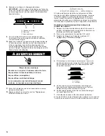
Electrical Shock Hazard

Plug into a grounded 3 prong outlet.
Do not remove ground prong.
Do not use an adapter.
Do not use an extension cord.
Failure to follow these instructions can result in death, 
fire, or electrical shock.

WARNING

Summary of Contents for JGC2530E Series

Page 1: ...IMPORTANT Installateur Remettre les instructions d installation au propri taire Propri taire Conserver les instructions d installation pour r f rence ult rieure COOKTOP SAFETY 2 Tools and Parts 4 Conv...

Page 2: ...afety messages will follow the safety alert symbol and either the word DANGER or WARNING These words mean follow instructions instructions DANGER WARNING WARNING If the information in this manual is n...

Page 3: ...ected follow the What to do if you smell gas instructions In the State of Massachusetts the following installation instructions apply Installations and repairs must be performed by a qualified or lice...

Page 4: ...onversion kit shall be installed by a qualified service agency in accordance with the manufacturer s instructions and all applicable codes and requirements of the authority having jurisdiction If the...

Page 5: ...1 2 psi gauge 14 WCP or lower The cooktop must be isolated from the gas supply piping system by closing its individual manual shutoff valve during any pressure testing of the gas supply piping system...

Page 6: ...hat the electrode aligns with the notch or hole in the burner base The igniter electrode is ceramic and could break during installation of the burner base 9 Open shutoff valve in the gas supply line T...

Page 7: ...ner to locate the LP or NAT position Turn over the spring retainer so the NAT is showing on the bottom Snap the spring retainer back into the cap Reinstall the cap onto the regulator 4 If they are ins...

Page 8: ...ice simmer 7 Place LP gas orifice spuds in plastic parts bag for future use and keep with package containing literature 8 Replace burner bases and burner caps IMPORTANT Be sure that the electrode alig...

Page 9: ...has been factory set to the lowest position available to provide reliable and constant reignition of the burner However each burner can be adjusted For LP gas conversion Tighten clockwise screw C snug...

Page 10: ...ll out the conversion label and attach label to bottom of the cooktop next to the rating tag Do not cover the rating tag with the conversion label 9 Save the orifices removed from the cooktop along wi...

Page 11: ...e d c s et de blessures graves vous et d autres Tous les messages de s curit suivront le symbole d alerte de s curit et le mot DANGER ou AVERTISSEMENT Ces mots signifient AVERTISSEMENT Si les renseign...

Page 12: ...ctions Que faire dans le cas d une odeur de gaz Dans l tat du Massachusetts les instructions d installation suivantes sont applicables Les travaux d installation et r paration doivent tre ex cut s par...

Page 13: ...conversion doit tre install par le personnel qualifi d une agence de service en conformit avec les instructions du fabricant et les prescriptions de tous les codes en vigueur et des autorit s juridict...

Page 14: ...t s du circuit d alimentation en gaz Essai de pression de circuit 1 2 lb po 14 de colonne d eau ou moins La table de cuisson devra tre isol e des canalisations d alimentation en gaz par la fermeture d...

Page 15: ...on pour pouvoir les r utiliser ult rieurement 8 Remplacer les bases et chapeaux de br leur IMPORTANT Veiller aligner l lectrode avec l encoche ou le trou la base du br leur L lectrode d allumage est e...

Page 16: ...iner le ressort de retenue pour identifier la position LP ou NAT Retourner le ressort de retenue pour que la mention NAT soit au fond R installer le ressort de retenue dans le chapeau R installer le c...

Page 17: ...ler conserver ensemble le chapeau et la base de chaque br leur afin de s assurer que le chapeau et la base seront bien install s sur le br leur correct 6 Pour convertir les br leurs Placer le tourne c...

Page 18: ...ncelles se produisent jusqu l apparition d une flamme Contr le du fonctionnement des br leurs de la table de cuisson 1 Appuyer sur le bouton de commande et le tourner la position HI r glage lev Le gaz...

Page 19: ...vis situ e sur la face sup rieure du fond du robinet au moyen d un tournevis lame plate de 3 32 n 0 2 0 mm jusqu ce que la flamme atteigne la taille ad quate 5 R installer le bouton de commande 6 R p...

Page 20: ...W10821220A 2015 Jenn Air Used under license in Canada All rights reserved Utilis sous licence au Canada Tous droits r serv s 10 15...

Reviews: