INSTALLATION
(1) Insert the replacement bulb in the lamp base
socket. Rotate it clockwise.
(2) Connect the wire harness connector to the
lamp.
VISOR VANITY LAMP BULB
REMOVAL
(1) Using a small flat blade, carefully pry each cor-
ner of lens outward from lamp.
(2) Separate lens from lamp.
(3) Grasp bulb and pull outward.
INSTALLATION
(1) Position bulb in socket and push into place.
(2) Position lens on lamp and snap into place.
OVERHEAD CONSOLE READING LAMP BULB
REMOVAL
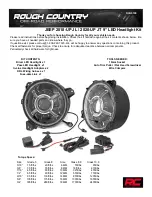
(1) Insert a flat blade screwdriver in slot at front
of lens (Fig. 4).
(2) Rotate the screwdriver until lens snaps out of
the housing.
(3) Remove lens from housing.
(4) Remove bulb from terminals.
INSTALLATION
(1) Insert bulb into reading lamp terminals.
(2) Replace lens by holding lens level and pushing
rearward into housing.
(3) Push lens up to snap into housing.
DOME LAMP BULB
REMOVAL
(1) Insert a flat blade screwdriver in slot at front
of lens.
(2) Rotate the screwdriver until lens snaps out of
the housing.
(3) Remove lens from housing.
(4) Remove bulb from socket.
INSTALLATION
(1) Insert bulb into reading lamp terminals.
(2) Replace lens by holding lens level and pushing
rearward into housing.
(3) Push lens up to snap into housing.
READING LAMP BULB
REMOVAL
(1) Insert a flat blade screwdriver in slot at front
of lens.
(2) Rotate the screwdriver until lens snaps out of
the housing.
(3) Remove lens from housing.
(4) Remove bulb from terminals.
INSTALLATION
(1) Insert bulb into reading lamp terminals.
(2) Replace lens by holding lens level and pushing
rearward into housing.
(3) Push lens up to snap into housing.
DOOR COURTESY LAMP BULB
REMOVAL
(1) Remove door trim panel. Refer to Group 23,
Body Components for service procedure.
(2) Remove bulb socket from lamp.
(3) Pull bulb from socket.
INSTALLATION
(1) Position bulb in socket and press into place.
(2) Install bulb socket in lamp.
(3) Install door trim panel.
CARGO LAMP BULB
REMOVAL
(1) Insert a flat blade screwdriver in slots provided
at lower portion of lens.
(2) Rotate screwdriver upward until lens snaps out
of housing.
(3) Remove lens from housing.
(4) Remove bulb from bulb socket.
INSTALLATION
(1) Position bulb in socket and press into place.
(2) Insert upper tabs of lens into lens housing.
(3) Snap lower portion of lens into slots at lens
housing.
Fig. 4 Overhead Console Reading Lamp Bulb
LENS
FLAT BLADE
CONSOLE
8L - 12
LAMPS
ZG
REMOVAL AND INSTALLATION (Continued)
Summary of Contents for 1997 Grand Cherokee
Page 6: ...FASTENER IDENTIFICATION 4 INTRODUCTION ZG GENERAL INFORMATION Continued ...
Page 9: ...METRIC CONVERSION ZG INTRODUCTION 7 GENERAL INFORMATION Continued ...
Page 12: ......
Page 58: ......
Page 180: ......
Page 228: ......
Page 274: ......
Page 282: ...COOLING SYSTEM DIAGNOSIS DIESEL ENGINE 7 8 COOLING SYSTEM ZG DIAGNOSIS AND TESTING Continued ...
Page 283: ...ZG COOLING SYSTEM 7 9 DIAGNOSIS AND TESTING Continued ...
Page 284: ...7 10 COOLING SYSTEM ZG DIAGNOSIS AND TESTING Continued ...
Page 285: ...ZG COOLING SYSTEM 7 11 DIAGNOSIS AND TESTING Continued ...
Page 286: ...7 12 COOLING SYSTEM ZG DIAGNOSIS AND TESTING Continued ...
Page 290: ...SERPENTINE DRIVE BELT DIAGNOSIS 7 16 COOLING SYSTEM ZG DIAGNOSIS AND TESTING Continued ...
Page 318: ......
Page 330: ......
Page 340: ......
Page 402: ......
Page 423: ...VIC Initial Set Up ZG INSTRUMENT PANEL SYSTEMS 8E 21 SERVICE PROCEDURES Continued ...
Page 424: ...VIC Reset 8E 22 INSTRUMENT PANEL SYSTEMS ZG SERVICE PROCEDURES Continued ...
Page 436: ......
Page 454: ......
Page 468: ......
Page 470: ......
Page 510: ......
Page 520: ......
Page 532: ......
Page 560: ......
Page 572: ......
Page 580: ......
Page 596: ......
Page 610: ......
Page 622: ......
Page 680: ......
Page 700: ......
Page 712: ......
Page 752: ......
Page 772: ......
Page 780: ......
Page 842: ......
Page 852: ......
Page 868: ......
Page 872: ......
Page 890: ......
Page 908: ......
Page 974: ......
Page 1056: ......
Page 1090: ......
Page 1104: ......
Page 1106: ......
Page 1118: ......
Page 1136: ......
Page 1176: ......
Page 1196: ......
Page 1208: ......
Page 1248: ......
Page 1268: ......
Page 1270: ......
Page 1271: ......
Page 1272: ......
Page 1273: ......
Page 1274: ......
Page 1276: ......
Page 1338: ......
Page 1348: ......
Page 1364: ......
Page 1368: ......
Page 1386: ......
Page 1404: ......
Page 1470: ......
Page 1492: ......
Page 1542: ......
Page 1552: ......
Page 1584: ......
Page 1598: ......
Page 1655: ...Fig 3 Oil Lubrication System ZG 5 2L ENGINE 9 57 DESCRIPTION AND OPERATION Continued ...
Page 1684: ...TORQUE 9 86 5 2L ENGINE ZG SPECIFICATIONS Continued ...
Page 1689: ...Fig 3 Oil Lubrication System ZG 5 9L ENGINE 9 91 DESCRIPTION AND OPERATION Continued ...
Page 1723: ...DIAGNOSIS AND TESTING SERVICE DIAGNOSIS DIESEL PERFORMANCE ZG ENGINE 9 3 ...
Page 1724: ...9 4 ENGINE ZG DIAGNOSIS AND TESTING Continued ...
Page 1725: ...ZG ENGINE 9 5 DIAGNOSIS AND TESTING Continued ...
Page 1726: ...9 6 ENGINE ZG DIAGNOSIS AND TESTING Continued ...
Page 1727: ...ZG ENGINE 9 7 DIAGNOSIS AND TESTING Continued ...
Page 1728: ...9 8 ENGINE ZG DIAGNOSIS AND TESTING Continued ...
Page 1729: ...SERVICE DIAGNOSIS DIESEL MECHANICAL ZG ENGINE 9 9 DIAGNOSIS AND TESTING Continued ...
Page 1730: ...9 10 ENGINE ZG DIAGNOSIS AND TESTING Continued ...
Page 1731: ...ZG ENGINE 9 11 DIAGNOSIS AND TESTING Continued ...
Page 1762: ...SPECIFICATIONS ENGINE SPECIFICATIONS 9 42 ENGINE ZG ...
Page 1763: ...ZG ENGINE 9 43 SPECIFICATIONS Continued ...
Page 1862: ......
Page 1930: ......
Page 1934: ......
Page 2114: ......
Page 2122: ...DIAGNOSIS AND TESTING NV231 DIAGNOSIS 21 8 TRANSMISSION AND TRANSFER CASE ZG ...