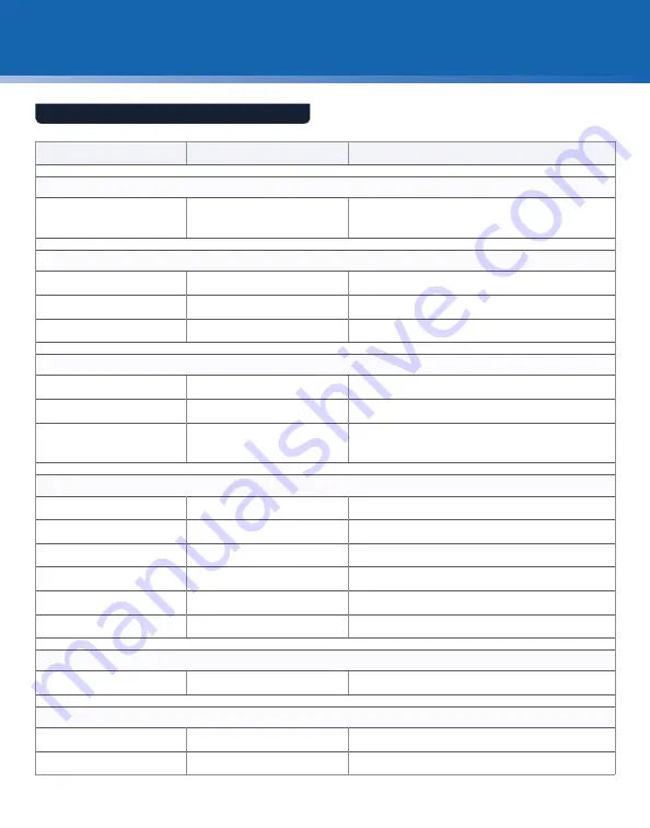
background image

22

User ManUal

troUBleshootInG

Symptom

Potential Cause

Test / Remedy

A – unit will not turn ON

No power to unit

•  Make sure power cord is connected.
•  Make sure power switch is in the correct position.

B – unit is ON, but will not fire


Power light is blinking

Run button

 on handset is depressed

•  Turn OFF power, release 

run button,

 and turn unit ON


Power light is solid RED

Safety is not disengaged

•  Apply pressure to cleaning nozzle to disable safety

            Low Solvent light ON

Solvent tank is empty

•  Refill the tank with cleaning solvent

C – unit fires but no solvent is dispensed

Solvent refill cap may be open

•  Close solvent refill cap

Line may need to be PRIMED

•  Prime the system 

(see page 16)

Cleaning tip damaged or plugged

•  Place the tip in electrostatic wash; if problem persists, 

replace tip

D – unit operates but doesn't clean properly

No cleaning tip or wrong tip installed •  Verify correct cleaning tip and install

Tip not fully inserted into bulkhead

•  Make sure the tip comes to a stop inside mating adapter

No solvent spray

•  See Symptom C above for remedy

Vacuum flow restricted

•  Check exhaust port or filter for obstruction

Air flow restricted

•  Check air filters

Nozzle damaged

•  Check nozzle inside tip for damage and replace if necessary

E – Service light is ON

System at service interval

•  Replace air filters

 (see page 21)

F – No image on LCD

No power to LCD

•  Verify the unit and LCD power switches are ON

No probe connected to unit

•  Install probe to probe input

TROuBLEShOOTINg TIPS

Summary of Contents for CleanBlast FCL-P1005

Page 1: ...ber inspection and cleaning procedures documented in this manual are recommendations made by JDSU Please reference your company s process documents for standard tools and methods for your specific app...

Page 2: ...s of Corning Incorporated Sony is a registered trademark of Sony Corporation Specifications terms and conditions are subject to change without notice All trademarks and registered trademarks are the p...

Page 3: ...rs 15 Bulkhead Inspection 12 Patch Cord Inspection 13 Zones and Acceptance Criteria 14 Grading Process 14 Bulkhead Cleaning 16 Patch Cord Cleaning 17 Good Fiber Connection 18 Fiber Connections 18 Sing...

Page 4: ...way to determine if fiber connectors are truly clean before mating them JDSU s video fiber inspection probe and CleanBlast system are used to quickly and easily inspect and clean connector end faces T...

Page 5: ...key mechanism that aligns the fiber and prevents the rotation of ferrules of two mated connectors Ferrule Thin cylinder where the fiber is mounted that acts as the fiber alignment mechanism the end of...

Page 6: ...creating unacceptable insertion loss and back reflection Furthermore these contamination particles can permanently damage the glass interface by digging into the glass and leaving pits when mated cau...

Page 7: ...g debris into the fiber Cleaned Fiber Before Embedding Debris Cleaned Fiber with Embedded Debris After Mating and Multiple Cleanings If dirty connectors are not inspected and cleaned prior to mating d...

Page 8: ...re devices This eliminates the need to disassemble hardware devices prior to inspection Focus Control Magnification Control Inspection Tip Barrel Assembly Standard Patch Cord Tips Standard Bulkhead Ti...

Page 9: ...mination from the end face along with the solvent are then removed through the retrieval circuit The precise highly efficient non contact air solvent air stream blasts and removes loose debris with ne...

Page 10: ...on Press this button to switch and select Brightness Contrast Color Tint and Reset modes Up Down Selector Press the Mode Button to select mode then press this button to adjust level of image quality e...

Page 11: ...e To clean the SOCKET side 1 Seat the tip over one of the sockets 2 Pull the safety trigger to depress the safety release button 3 Apply slight pressure and push the handset into the insert until it s...

Page 12: ...on page 26 4 Insert the probe into the bulkhead to inspect 5 Turn the focus control on the probe to focus the fiber image on the display 6 Determine whether clean or dirty If clean do not touch it and...

Page 13: ...uide on page 26 4 Attach the patch cord to the probe to inspect 5 Turn the focus control on the probe to focus the fiber image on the display 6 Determine whether clean or dirty If clean do not touch i...

Page 14: ...ector end face The inner most zones are more sensitive to contamination than the outer zones Acceptance criteria are a series of failure thresholds that define contamination limits for each zone A Cor...

Page 15: ...one Name Diameter Defects Scratches A Core Zone 0 65 m 4 5 m none 5 m no limit 5 m 0 5 m B Cladding Zone 65 120 m no limit 2 m 5 from 2 5 m none 5 m no limit 5 m 0 5 m C Adhesive Zone 120 130 m no lim...

Page 16: ...he bulkhead 4 Determine whether clean or dirty If clean do not touch it and CONNECT If dirty repeat CLEAN Note Embedded mated debris cannot be cleaned and bonded burned debris must be physically clean...

Page 17: ...n green and press the run button to initiate cleaning 3 INSPECT the patch cord 4 Determine whether clean or dirty If clean do not touch it and CONNECT If dirty repeat CLEAN Note Embedded mated debris...

Page 18: ...y throughout optical networks They give us the ability to re configure the network and provision services If contamination is present in the light path system performance will be degraded Always inspe...

Page 19: ...oir must be refilled before operation can resume see page 20 for solvent refill procedures The reservoir will hold 225 ml 8 fl oz of solvent enough for at least 8 000 cleaning cycles Note Do not refil...

Page 20: ...o disconnect the bottle and rotate the refill cap to original position and turn the system ON 6 Prime the system see page 16 Cap Lock 2 3 Solvent Refill Cap Assembly Cleaning Solvent Bottle see page 2...

Page 21: ...th a flat head screwdriver unscrew and remove the 2 air filters and replace with new filters FCLP FA F1 6 Replace the water trap bowls tighten the drain valves and replace the release knobs 7 With a p...

Page 22: ...need to be PRIMED Prime the system seepage16 Cleaning tip damaged or plugged Place the tip in electrostatic wash if problem persists replace tip D Unit operates but doesn t clean properly No cleaning...

Page 23: ...pressure if stored shipped under elevated temperature Open closure slowly to vent pressure Contact 3M for the most current safety information and MSDS Reference 3M part number HFE 72DA The following f...

Page 24: ...t enclosure has been opened other than as explained in this manual The equipment serial number has been altered erased or removed The equipment has been misused neglected or accidentally damaged This...

Page 25: ...ning tip 6 4 in LCD EU power FCL P2100 CleanBlast portable with 5 ft umbilical 90 bulkhead handset USB 1 1 output universal 2 5 mm cleaning tip FCL P2102 CleanBlast portable with 5 ft umbilical 90 bul...

Page 26: ...FC UPC connectors through a bulkhead barrel assembly required ST UPC FBPT ST Inspect ST UPC connectors through a bulkhead barrel assembly required LC UPC FBPT LC L Inspect LC UPC connectors through a...

Page 27: ...ors through a bulkhead ST UPC FCLT U25 Clean 2 5 mm UPC and APC connectors through a bulkhead LC UPC FCLT U12 Clean 1 25 mm UPC and APC connectors through a bulkhead FCLT U12 MA FCLT U12 Clean 1 25 mm...

Page 28: ...ssumes all risks and liability whatsoever in connection with the use of a product or its applications JDSU reserves the right to change at any time without notice the design specifications function fi...

Reviews: