maintenance instructions
page 8 of 12
Model AN--10K1
JARVIS
6244001:
®
PRODUCTS CORPORATION
33 ANDERSON ROAD, MIDDLETOWN, CONNECTICUT 06457--4926
UNITED STATES OF AMERICA E--MAIL.
TEL. 860--347--7271 FAX. 860--347--6978 WWW. j
arvisproducts.com
1
DAILY:
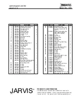
1.1 Check tightness and condition of hex head
screws (item 3) and socket head screws (item 60).
Replace if necessary.
1.2 Check condition and operating smoothness of
trigger contact bushing (item 1), trigger firing
shaft assembly (item 44), release valve assembly
(item 37), rocker lever (item 40) and trigger lever
(item 42). Lubricate or replace if necessary.
2
WEEKLY:
2.1 Check condition of housing cover (item 58). Re-
place if necessary.
2.2 Check condition of catch bushing (item 55). Re-
place if necessary.
Refer to penetrating shaft dis-
assembly, section 3.
2.3 Check condition of o--rings (item 53), valve case
(item 54), packing ring (item 50) and upper valve
sleeve (item 49) for dirt, wear or damage. Re-
place if necessary.
Refer to penetrating shaft dis-
assembly, section 3.
2.4 Check condition of bumper (item 11). Replace if
necessary.
Refer to bumper disassembly, section
5.
Note: Bumper has an approximate service life of 5000 --
6000 cycles.
2.5 Check end of penetrating shaft (item 27) for wear
or damage. Replace if necessary.
Refer to pene-
trating shaft disassembly, section 3.
2.6 Wash all parts thoroughly and lubricate with
SAE 10 oil approved for USDA H1 service.
3
PENETRATING SHAFT DISASSEMBLY:
3.1 Remove shoulder screws (item 6) and hex lock
nuts (item 46) from hanger bracket (item 5).
3.2 Remove safety bracket (item 61) and hanger
bracket (item 62).
3.3 Remove socket head screws (item 60) that secure
housing cover (item 58) to unit.
3.4 Remove housing cover (item 58).
3.5 Remove o--ring (item 57) and air deflector (56).
3.6 Remove penetrating shaft assembly (items
23--27)
.
3.7 Remove catch bushing (item 55).
3.8 Remove o--rings (item 53), valve case (item 54),
packing ring (item 50) and upper valve sleeve
(item 49).
3.9 Remove special nut (item 25), o--ring (item 24),
locking piston (item 26) and piston spacer (item
23) from penetrating shaft (item 27).
4
PENETRATING SHAFT INSTALLATION:
4.1 Reverse steps and procedures outlined in section
3.
See special notes below:
4.1.1 Make sure safety bracket (item 61) and hang-
er bracket (item 62) are correctly installed
onto hanger bracket (item 5).
4.1.2
Install and tighten hex lock nuts (item 46)
to 7.4 lbf--ft (10 N--m)
.
4.1.3
Install and tighten socket head screws
(item 60) with lock waster (item 59) to 7.4
lbf--ft (10 N--m)
.
4.1.4 Make sure o--ring (item 57) is correctly
installed into groove of housing cover (item
58).
Adhesive may be used to install the o--
ring into the groove.
5
BUMPER DISASSEMBLY:
5.1 Remove shoulder screws (item 6) and hex lock
nuts (item 46) from hanger bracket (item 5).
5.2 Remove safety bracket (item 61) and hanger
bracket (item 62).
5.3 Remove socket head screws (item 60).
5.4 Remove housing cover (item 58).
5.5 Remove o--ring (item 57) and air deflector (56).
5.6 Remove penetrating shaft assembly (items
23--27, and 49--55)
.
5.7 Remove sliding valve (item 22), housing cylin-
der (item 30) and muffler (item 31).


