4 - 16
emPC-X
(
Hardware Manual
)
•
Installation
©
Janz Tec AG
Rev. 1.2
4.2
RS232
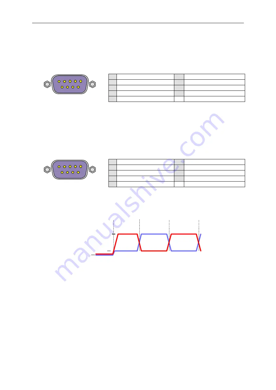
Additional serial interfaces might be implemented by a XR16V2750
dual UART chip. This type of serial
port has proprietary implementation over the internal expansion bus. Hence it needs special software
driver. For a description of UART registers refer to the EXAR manual. The UART clock input is
14,7456MHz to allow error free generation of standard baud rates. This RS232 variant provides all 8
interface signals as shown in table 8.
9pin male D-Sub
1 DCD
6 DSR
2 RxD
7 RTS
3 TxD
8 CTS
4 DTR
9 RI
5 GND
table 8: RS232 connector
4.3
RS485
In the RS485 variant, there are only the differential signals D+ and D- provided. The transceiver is
enabled to send data, when RTS# of the corresponding UART is low. Hardware can be customized to
either receive or not-receive (standard) the transmitted data on the UART
’s RxD input. Ask Janz Tec
for customization regarding this option.
9pin male D-Sub
1 n.c.
6 GND
2 D+
7 D-
3 GND
8 n.c.
4 n.c.
9 n.c.
5 n.c.
table 9: RS485 connector
The bidirectional differential signals D+ and D- are provided. When the transmitter is enabled, and no
data is send (1=MARK), then D+ > D- (refer to figure 8 ).
Note that D+ corresponds to pin “A” of the transceiver chip. However, this is signal B according to the
EIA-485 or Profibus standards.
The receiver has the failsafe input feature, which ensures that no data is received when D+ and D- are
floating or are shorted (e.g. by the termination resistor).
D+
D-
1 = Mark
0 = Space
1 = Mark
Transmitter
idle
Startbit
Databit 0
Transmitter
tristate
"0V"
Voh
Vol
figure 8: RS485 signaling
1
6
1
6
Summary of Contents for emPC-X Series
Page 6: ......


