


(A)
(B)
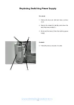
Replacing Printed Circuit Boards F1, F2 and Slide Volume
Printed circuit board F1
To remove:
1. Remove the front cover.
2. Pull out the connector from printed circuit board
A.
3. Remove the 2 screws (A) and remove printed cir-
cuit board F1 (1).
To attach:
4. Follow the above procedure in reverse.
Printed circuit board F2
To remove:
1. Remove the front cover.
2. Pull out the connector from printed circuit board
A.
3. Remove the 3 screws (B) and remove printed cir-
cuit board F2 (2).
To attach:
4. Follow the above procedure in reverse.
Slide volume
To remove:
1. Remove the front cover.
2. Pull out the slide volume connector from printed
circuit board A.
3. Remove the 2 CS rings (3) and remove the slide
volume (4).
To attach:
4. Follow the above procedure in reverse.
(1)
(2)
(3)
(4)
13
www.promelectroavtomat.ru