background image

JPC70


www.janitza.com

16

7. 

Configuration

Operation of the device takes place either 
on the device itself via touch screen or via 
remote access with the PC connected to the 
device in the network.

7. 1 

Start screen

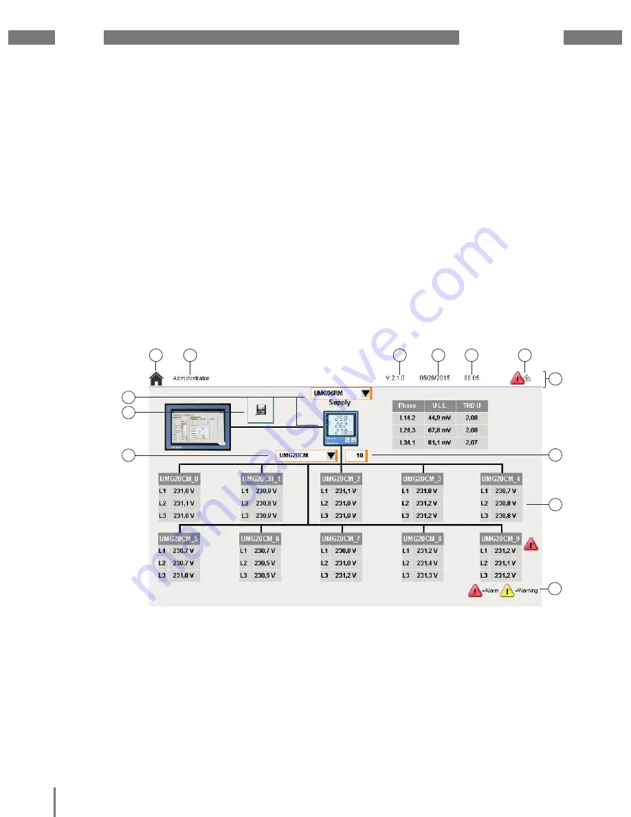
A topology overview of the integrated bus 
system is represented on the main screen of 
the device.

An overview of the current voltage values of 
the integrated slave devices is shown on the 
start screen.

By touching the values in the overview of 
a slave device, you open its other values, 
the configuration menu and the alarm 
configuration for this device.

1


Selected slave device

2


Save

 button

3


Selected master device

4


Home

 button

5


Active user role

6


Software version

7


Current date

Fig. 11: Start screen

1

2

3

4

5

6

7

8

9

11

10

12

13

8


Current time

9

 Warnings/alarms

10


Status bar

11


Number of slave devices

12


Representation of a slave device

13

 Legend

Summary of Contents for JPC70

Page 1: ...8 Smart Energy Panel JPC70 User Manual and Technical Data Janitza electronics GmbH Vor dem Polst ck 6 35633 Lahnau Germany Support tel 49 6441 9642 22 Fax 49 6441 9642 30 Email info janitza com www ja...

Page 2: ...ription 8 4 1 Operating concept 8 4 2 Performance features 9 4 3 Product overview 10 5 Assembly 12 5 1 Installation location 12 5 2 Installation position 12 5 3 Fastening 12 5 4 Ground 13 6 Installati...

Page 3: ...User management 25 7 6 1 User settings 25 7 7 System 27 7 7 1 Device settings 27 7 7 2 Modbus TCP 27 7 7 4 Time setting 28 7 7 5 Display 28 7 7 3 TCP IP settings 28 7 8 Email configuration 29 8 Servi...

Page 4: ...belong to the respective holders of these rights 1 3 Technical changes Make sure that the installation instructions match your device First make sure you have read and understood the document accompa...

Page 5: ...l must be read the manual before using the device must be kept and remain available for reference during the entire service life of the product Also observe the applicable legal and safety requirement...

Page 6: ...ltages present in the device even after it is disconnected from the supply voltage Fit wire end ferrules on the conductors made of individual wires Only connect screw type terminals with matching numb...

Page 7: ...when for example the device has visible damage no longer functions despite an intact power supply was subjected to extended periods of unfavorable conditions e g storage outside of the permissible cl...

Page 8: ...vices installation in permanently installed switch cabinets or small installation distributors 4 1 Operating concept You can program the device in several different ways and or display measured values...

Page 9: ...t interface Operating temperature range 20 C 60 C Visualization Representation of all current and energy values Display of the last maximum value of the connected devices Topology view of the bus syst...

Page 10: ...capable a mean value is generated when the screen is touched in multiple places simultaneously This averaged position value is evaluated by the application Therefore since the entire touch area is lar...

Page 11: ...ctor The connection to the ground potential must be made as short as possible and adequately strong 4 mm via the provided flat plug connection Faston 6 3 mm 2 Unshielded conductors All unshielded cond...

Page 12: ...free surface Unevenness can cause damage to the display and result in the penetration of dust and water Fig 4 Rear view with retaining clamps 1 Insert the front side of the device in the provided ins...

Page 13: ...g The cable shield e g Ethernet is discharged via the ground plate Ground connection WARNING The ground potential ground lug on the device and the GND connection of the voltage supply are connected in...

Page 14: ...via the plug type terminals on the rear side of the device Before connecting the supply voltage ensure that the supply voltage matches the specifications form the technical data See section 9 on Page...

Page 15: ...egments Slave Fig 10 Bus structure representation Slave Slave Slave Repeater Slave Slave Slave Master Speisung notwendig power supply necessary Busabschluss eingeschaltet bus terminator on T T T T T D...

Page 16: ...rent voltage values of the integrated slave devices is shown on the start screen By touching the values in the overview of a slave device you open its other values the configuration menu and the alarm...

Page 17: ...igning a permanent IP address can cause problems in networks See 7 7 3 on Page 28 7 2 1 Integrating the master device Proceed as follows to connect the device to a master 1 Log in as an administrator...

Page 18: ...determine the Modbus address 8 Configure the addresses of all connected slave devices in this manner 9 Save the settings by pressing the Save button 10 Touch the version number date or time in the st...

Page 19: ...is purpose open the configuration menu of a slave device as described in 7 2 2 Fig 15 Measured values overview You switch between the available measuring channels of the device with the arrow buttons...

Page 20: ...gured with the JPC70 With the Set IO selection box you can define whether outputs should be activated when the warning level or alarm level is exceeded Low pass filter You can activate the low pass fi...

Page 21: ...devices connected in the bus Fig 18 Configuration interface of the slave devices in the JPC70 Here you have the option to adopt energy meters and minimum maximum current values for all slave devices...

Page 22: ...more information refer to the user manual of the slave device In the process the threshold values for triggering a warning and threshold values for trigging an alarm are defined If the respective thre...

Page 23: ...e to activate deactivate the alarm system It is possible to receive messages via email in addition to the messages on the JPC70 See 7 8 Email configuration on Page 29 7 4 Master devices Call up additi...

Page 24: ...bar Messages can be acknowledged individually with the Acknowledge selected alarm button or all at once by pressing the Acknowledge all alarms button 7 5 1 Alarm history You open the alarm history by...

Page 25: ...gs can be acknowledged Operator Standard role for logged in users They can also acknowledge and configure alarms and warnings in addition to the ViewOnly user Administrator Device settings can be carr...

Page 26: ...the User name input field 5 Enter the user s fill name in the Full name input field optional 6 Select the desired role in the Group role selection list 7 Select the system language for the new user i...

Page 27: ...ings of a device and importing them to another device For this purpose proceed as follows 1 Connect the JPC70 via one of the USB interfaces to a FAT32 formatted USB data carrier The check mark next to...

Page 28: ...ton next to the IP address input field 4 Press the Save button to save the configuration 7 7 4 Time setting The time for the JPC70 can be entered manually with the Clock menu item or obtained via an N...

Page 29: ...ail proceed as follows 1 Enter the host address of the email server in the Host IP input field 2 Enter the valid login data for the email server in the User name and Password input fields Learn about...

Page 30: ...ulations e g as Electronic waste Plastic Metal or commission a certified disposal company with the scrapping 8 4 Service In case of any questions which are not described in this manual please contact...

Page 31: ...100BASE TX Display Type Color TFT Diagonal 7 Colors 16 7 million RGB 8 bits per channel Resolution WVGA 800 x 480 pixels Contrast typically 600 1 Touchscreen Yes Electrical properties Supply voltage...

Page 32: ...170 73 26 27 27 8 184 8 112 9 42 8 170 73 26 27 27 8 184 8 112 9 150 5 140 197 5 25 5x 12 5 13 8 1 127 9 42 8 R2 Fig 28 View from above Fig 29 Front view Fig 30 Rear view 170 73 26 27 27 8 184 8 112...

Reviews: