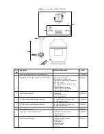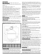
FIGURE 2 -
Sand Fill Cover Assembly
Clamp Screw
Clamp
Clamp Bolt
O’ring
FIGURE 3 -
7 Position
Dial Valve Installation
Clamps are
completely closed
FIGURE 4 -
Clamp Installation
3). Place the sand fi ll cover over the tank opening to prevent the sand from
getting into the standpipe.
See fi gure 2.
4).
Fill the tank approximately 1/2 full of water.
5).
Pour the recommended amount of sand into the tank, making sure that the
standpipe remains centered and vertical. Level the surface upon completion.
6).
Remove the sand-fi ll cover.
7).
Pre-assemble the clamps with one screw and one nut, turning the screw 3-4
turns only. See fi gure 3.
8).
Carefully remove all sand particles from the valve mounting surfaces.
9).
Place the O-Ring onto the bottom of the valve body.
10).
Lower the dial valve carefully into position so that its underside engages with
the standpipe. Rotate the valve until the inlet is approximately in line with the pump.
11).
Place clamps around tank and valve neck and assemble second screw and nut.
12).
Firmly tap with a rubber mallet outside of the clamps as you tighten both screws
alternately and evenly.
13).
Make sure screws are tightened until clamps are completely closed.
See fi gure 4.
14).
Install the pressure gauge into the threaded opening in the dial valve. Do not
overtighten.
15).
Install the backwash adapter in the dial valve port marked “waste”.
PLUMBING CONNECTIONS
The provision of gate valves and unions in the pump suction and pool return
lines of a permanent installation will make servicing easier and prevent loss of
water while routine maintenance is in progress. Pump Installation: Follow the
instructions supplied with the pump. Connect the pipes to the fi lter system as
shown on page 3. Do not use pipes smaller than the connections provided.
Support the plumbing so that it puts no strain on either the pump or the fi lter.
FOR SOLVENT WELD CONNECTIONS
Rigid or fl exible PVC pipe can be used. Pipe ends should be clean and free of any
debris caused by the cutting operation. Be sure that the proper adhesive is used
on the type of pipe specifi ed. Recommended Adhesives: These are examples
only and are not intended to restrict brands:
PVC-PVC Joint
PVC-ABS Joint
Uni-Weld Pool-Tite 2000
Uni-Weld Pool-Tite 2000
Suregard Flex 20
Suregard Weld-All No. 5
IPS Weld-On 705
IPS Weld-On 794
Note:
A primer will assure that adhesive joints are superior. Suregard P-3000 has
a purple tracer to qualify in areas where codes specify a primer must be used.
Caution:
We recommend that you consider climatic conditions when applying
adhesives. Certain atmospheric situations, such as high moisture content, make
the adhesive action of certain glues less effective. Check the manufacturer’s
instructions.
FOR THREADED CONNECTIONS
Use only Tefl on tape or equivalent on threaded plumbing connections. Other
pipe compounds may damage threads. We do not recommend the use of silicone
or petroleum based compounds. DO NOT OVERTIGHTEN: HAND-TIGHTEN PLUS
1/2 TURN IS SUFFICIENT.
FILTER PLUMBING
If the fi lter is equipped with union connections, union adapters are needed to
complete plumbing connections and may need to be ordered separately.
START-UP PROCEDURE
After completing the preceding items and fi lling the pool with water, put the system
into operation as described below.
When the fi lter system is below deck level,
always close the gate valves in the pump suction and pool return lines before you
remove the cover from the hair and lint strainer. Re-open the valves before you
restart the pump.
1a). For in-ground pools
: Set the dial valve to WINTERIZE. Remove the cover
from the hair and lint strainer, and fi ll the pump with water. Refi t the cover and
strainer Ring-Lok
TM
- hand tighten only -
do not re-tighten strainer Ring-Lok
TM
during operation.
1b). For above-ground pools:
When the water level in the pool reaches the skimmer
and return fi tting, the fi lter and pump will begin fi lling with water. Some air may be
trapped in the pump or fi lter, but will be removed when the pump is started.
Removing the pressure gauge temporarily while the fi lter is fi lling with water will
also help remove any trapped air. Replace the pressure gauge when a steady
stream of water appears.
2).
Set the dial valve to DRAIN position.
3).
Perform pump start-up.
4).
After a good fl ow has been established, continue pumping for one minute or
until wastewater is clear, then stop the pump.
5).
Set the dial valve to BACKWASH, and start the pump. The pump should deliver
a strong stream of water as soon as it has removed the air from the suction system.
Should the pump fail to prime within two or three minutes, stop the pump and
repeat steps 1 and 2.
6).
After a proper fl ow of clean water has been established, operate the fi lter with
the dial valve set to DRAIN, WHIRLPOOL and RINSE for ONE minute each in that
order. Stop the pump before changing valve positions.
7).
Set the dial valve back to FILTER. After the fi lter has operated for about 10
minutes, check the pool return fi tting for air bubbles. A continuous fl ow of air
indicates a leak in the suction system, which must be corrected immediately.
5


