background image

3

Content

Safety Information 

3

General Information 

3

Technical data 

3

Box contents/Features 

5

Disposal information 

5

Communications regulations 

5

Disposal informations 

5

Safety Information

Models are not toys, and should only be operated by responsible 
clear thinking people. Assembling and maintaining models requires 
a basic level of technical skill, and a sensible logical approach. Any 
error in building, repairing or maintaining the model could result in 
serious injury or damage. 
Technical problems or an incorrectly assembled model may lead to 
the propeller unexpectedly beginning to turn. Always stay out of 
the vicinity of rotating parts and never allow any item to come into 
contact with a spinning prop. As neither the manufacturer or the 
dealer has any influence over the way that models are operated 
they can accept no responsibility for and damage caused. 
If this model is the first radio controlled model which you are att-
empting to build or drive, you should secure the assistance of an 
experienced model pilot.
Never operate the model lin way which may endanger people or 
animals. Before your first drive you should conduct a range check 
of the radio control system, secure the model to a solid object, and 
ensure that you have full control of all functions with the antenna 
collapsed over a distance of at least 25 metres.  
Before and after every drive inspect the model for damage, and 
rectify any faults before you attempt to take off. The operator is 
responsible for any damage caused by the operation of models. 
Always observe any local laws regarding the operation of model. To 
operate the model, the transmitter must be switched on first, and 
then the model power supply connected. To turn the model off, re-
verse the procedure. It is illegal to operate radio controlled models 
without third party liability insurance. You must ensure that you are 
adequately covered before you drive the model.

Furthermore, the following instructions must be followed: 

-  The kit contains small parts which may cause choking if
  swallowed, keep away from small children. 
-  The model should not be changed in any way, doing so
  will invalidate the guarantee. 
-  Never come into contact with rotating parts. 
-  Do not expose the model or batteries to direct sunlight,
  always keep them in the shade. 
-  Inspect the model before and after every drive for
  damage. 
-  Only ever drive the model if it is in perfect working order. 
-  The model can only be drive in good weather. 


  Do not drive in wind, rain or thunder storms. 
-  Find a place to drive which complies with any laws, and is
  free from obstacles such as trees or houses. 
-  Remember that your model is made from such materials
  as plastic and wood, and as such is inflammable. Keep
  it away from any open flame, or high temperatures. 
-  When operating the model, switch on the transmitter
  first and then the aircraft, switch off in the reverse order. 
-  Always ensure that the throttle stick is in the low position
  before you switch on. 

General Information

Technical data

As the company JAMARA e. K. has no influence over the use, main-
tenance or conditions under which our products will operate, we 
accept no responsibility for any damage caused be it of a physical, 
financial or theoretical nature.  JAMARA e. K. will accept no claim 
against it which results directly or indirectly from the operation or  
use of ist products. 
Your Statutory Rights apply, any claim made against us will be based 
solely on the retail price of the product, and limited to the model 
only. This will not apply if we are proved to be legally responsible or 
when gross negligence can be proved.  

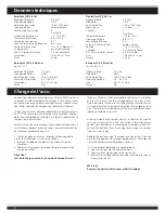
Dimensions 

approx. 470 x 390 x 280 mm

Weight 

approx. 4150 g 

Scale 

 1/8

Motor  

4,02 ccm 

Attention!

Switch the transmitter on first then the model. When you are fini-
sished first switch off the model then the transmitter.

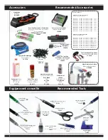
Recommended Accessories 

6

Recommended Tools 

6

Trasnmitter 

7 - 12

Assembly 

13 - 30

Setting Guide 

31

Parts 

32 - 33

Tuning parts 

34

Summary of Contents for Heart Attack 05 7130

Page 1: ...A NL GR B DK PL P FIN Notice d utilisation Veillez lire attentivement la notice d utilisation avant de mettre en marche votre modèle et de la conserver soigneusement même après l assemblage Instruction Read these instructions carefully before use Please keep these instruction after assembling Attention Ce modèle n est pas un jouet Ne convient pas aux enfants de moins de 14 ans Si vous êtes débutan...

Page 2: ... consig nes suivantes Ce modèle est composé de petites pièces contenues dans le kit pouvant êtres avalées par des enfants veillez donc à ce que celles ci ne puissent pas se trouver dans les mains de petits enfants Toute modification effectuée sur votre modèle est interdite et aura pour conséquence l annulation de la garantie Toutes manipulations au niveau de la structure du modèle est interdite et...

Page 3: ...that you are adequately covered before you drive the model Furthermore the following instructions must be followed The kit contains small parts which may cause choking if swallowed keep away from small children The model should not be changed in any way doing so will invalidate the guarantee Never come into contact with rotating parts Do not expose the model or batteries to direct sunlight always ...

Page 4: ...xtes de la directive européenne R TTE appareils de radio transmission FTEG 1999 5 EG WEEE appareils électroniques ou déchet électronique 2002 96 EG RoHS interdiction d utilisation de certain produits chimiques dangereux pour la réalisation des composants électroniques et pour la fabrication du matériel électronique 2002 95 EG X X Respectez les dispositions relatives aux télécommunications du pays ...

Page 5: ...rmity Relevant EEC Directives Radio Telecom Terminal Equipment R TTE 1999 5 ECC Waste Electrical and Electronic Equipment WEEE 2002 96 ECC Restriction of Hazardous Substances RoHS 2002 95 ECC X X X Communications Regulations Please observe all rules and regulations referring to the use of radio signals radio control which may be in force within the country where you are operating your model any qu...

Page 6: ...scosity 350 75 ml Réf Ord No 28 1904 Viscosité Viscosity 400 75 ml Réf Ord No 28 1905 Viscosité Viscosity 450 75 ml Réf Ord No 28 1906 Viscosité Viscosity 500 75 ml Réf Ord No 28 1907 Viscosité Viscosity 550 75 ml Réf Ord No 28 1908 Viscosité Viscosity 600 75 ml Réf Ord No 28 1909 Viscosité Viscosity 700 75 ml Réf Ord No 28 1910 Viscosité Viscosity 800 75 ml Huile silicone pour différentiel Silico...

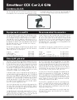
Page 7: ... est possible de relier votre émetteur directement à un PC ou un ordinateur portable au travers du port DSC Pour cela il vous faut le câble d interface USB en option Grâce à celui ci vous pouvez également utiliser votre émetteur pour les simulateurs Descriptif général Our Radio Control System CCX 2 4 GHz Car comes complete with transmitter matching 3 channel receiver and these instructions In orde...

Page 8: ...s de charge est achevé Attention Lors de la charge ouvrez le couvercle du compartiment If you use NiCad or NiHm rechargeable cells for your transmitter ensure that the cells are fully charged before using the system Please be aware that due to the self discharge characteristics of this type of cells that they should always be fully charged prior to use Please refer to the battery manufacturers rec...

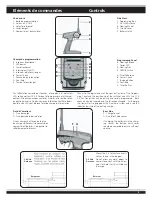
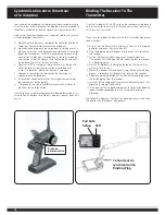
Page 9: ...partiment de piles Cela permet le refroidissement des accus F G Fixez l antenne de réception ver ticalement comme indiqué sur l illustration Il est interdit de fixer l antenne sur les pièces méca niques la portée serait raccourcie 2 4 GHz Antenne Récepteur 2 4 GHz Antenna Receiver Side View 1 Programming Box 2 2 4 GHz Antenna 3 Steering Wheel 4 Throttle Lever 5 Battery Hatch Programming Panel 6 St...

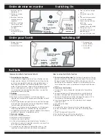
Page 10: ...hronisation et désigne les différents éléments devant êtres acti onnés As with all modern 2 4GHz R C systems the receiver must be bound to the transmitter to ensure that the receiver will only react to sig nals from that transmitter If you wish to re bind the receiver with the transmitter please pro ceed as follows A Ensure that the transmitter is fitted with fresh or fully charged batteries and l...

Page 11: ...out position and hold on d Press the setting button the LED will be flash for 3 seconds see on pict left e The setting is finished 3 Testing a Switch on the transmitter and enter the working condition b Contact the receiver with power and enter the working condi tion c Turn off the power of transmitter d The throttle of servo will be set automatically e Finish these steps above means the setting i...

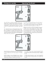
Page 12: ...ul sion électrique avec régulateur compatible marche arrière Direction Steering Gaz Trottle Lever Pilotage du modèle Operating The Model This function is used to steer the model and turning the steering wheel will make the models wheels to turn in the relevant direc tion Turning the wheel to the right will make the models wheels turn to right when viewed from above as illustrated Moving the wheel ...

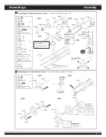
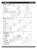
Page 13: ...tubes into the holes of the diff case Vissez en diagonale Tighten the diff Screws in this order Respectez le type de trou The straight holes are for the fr ont and rear only 05 1403 05 1402 env 10 mm approx 10 mm 05 1211 3 x 8 mm 05 1996 Notez la position d installation The holes for rear diff mount are width Notez la position d installation The holes for rear diff mount are width 05 1400 05 1400 ...

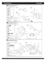
Page 14: ...ep 1 Step 2 5 x 4 mm 4 x 12 mm 051213 503703 051744 051263 051263 051201 051263 6 x13 x5 mm Roulement à bille Ball Bearing 2 x 4 x 12 mm Vis tête arrondie six pans creux Hex Screw 2 x 5 x 4 mm Vis six pans creux Set Screw 1 x Graisser Grease Graisser Grease Montage du corps de transmission avant Assembly of the front gear case 4 x 25 mm Vis tête fraisée six pans creux Flat Head Hex Screw 2 x 4 x 1...

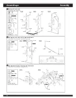
Page 15: ...3216 051773 4 x 10 mm Vis six pans creux Set Screw 2 x 2 5 mm Circlips E Ring 4 x 051758 7mm Rotule Ball 2 x 051759 5 x 35 mm Tige filetée parallélisme Turnbuckle 2 x 051447 3 x 44 3 mm Entretoise directionnelle Arm Shaft 2 x Step 1 Step 2 051758 051740 051759 051432 051447 503701 8 x 12 x 0 3 mm 4 x 4 mm 4 mm 4 mm env 9 5 mm Approx 9 5 mm 2 5 mm 2 5 mm 4 x 10 mm 3 mm Ecrou sécurisé Nylon Nut 2 x ...

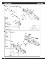
Page 16: ...sée six pans creux Flat Head Hex Screw 4 x 7 mm Boule Kugel 4 x 3 x 10 mm Vis tête arrondie six pans creux Hex Screw 3 x 8 x 12 x 1 mm Rondelle Washer 1 x 503707 6 mm Circlips E Ring 4 x 051746 Douille pour servo saver Servo Saver Bushing 2 x 3 x 16 mm Vis tête arrondie six pans creux Hex Screw 2 x Step 1 Step 2 Step 3 3 x 16 mm 503707 051746 503708 3 mm 051763 Servo saver complete complete 05 174...

Page 17: ...ns creux Flat Head Hex Screw 2 x 3 x 16 mm Vis tête arrondie six pans creux Hex Screw 2 x 3 mm Ecrou sécurisé Nylon Nut 2 x 051985 3 x 42 6 mm Entretoise directionnelle bas arrière extérieur Arm Shaft 2 x 2 5 x 16 8 mm Téton en pin Pin 2 x 5 x 4 mm Vis six pans creux Set Screw 2 x 3 5 x 8 5 x 3 mm Rondelle entretoise plastique Plastic Washer 4 x 3 x 5 mm Vis tête arrondie six pans creux Hex Screw ...

Page 18: ... 18 mm Vis tête arrondie six pans creux Hex Screw 2 x 3 mm Circlips E Ring 4 x 3 mm Ecrou sécurisé Nylon Nut 4 x Montage du stabilisateur arrière Assembly of the rear stabilizer rods Step 1 Step 2 3 x 8 x 0 8 mm Rondelle Washer 2 x 3 x 18 mm Vis tête arrondie six pans creux Hex Screw 2 x 3 x 8 mm Vis tête arrondie six pans creux Hex Screw 2 x 3 x 8 mm Vis six pans creux Set Screw 2 x 3 x 3 mm Vis ...

Page 19: ...18 mm 051401 051401 Step 2 Step 1 3 x 18 mm Vis tête arrondie six pans creux Hex Screw 2 x 2 x 18 mm Vis Screw 2 x 3 mm Ecrou sécurisé Nylon Nut 2 x 2 mm Ecrou Nut 2 x 3 x 18 mm Vis tête arrondie six pans creux Hex Screw 2 x 2 x 18 mm Vis Screw 2 x 3 mm Ecrou sécurisé Nylon Nut 2 x 2 mm Ecrou Nut 2 x Step 1 051401 051401 hier ab schneiden env 20 mm Approx 20 mm 3 mm 3 x 18 mm 2 x 18 mm 2 mm Step 2...

Page 20: ...4 x 16 mm Vis tête fraisée six pans creux Flat Head Hex Screw 4 x 4 x 12 mm Vis tête fraisée six pans creux Flat Head Hex Screw 2 x 3 x 25 mm Vis tête fraisée six pans creux Flat Head Hex Screw 2 x 3 x 10 mm Vis tête fraisée six pans creux Flat Head Hex Screw 2 x 4 x 16 mm Vis tête fraisée six pans creux Flat Head Hex Screw 4 x Mettre en place l axe avant l assemblage Insert drive shaft into cap j...

Page 21: ... 16 mm 3 x 8 mm 3 x 8 mm 3 x 16 mm Step 3 Step 1 Step 2 4 x 16 mm Vis tête fraisée six pans creux Flat Head Hex Screw 4 x 3 x 25 mm Vis tête fraisée six pans creux Flat Head Hex Screw 2 x 3 x 8 x 0 8 mm Rondelle Washer 8 x 3 x 16 mm Vis tête arrondie six pans creux Hex Screw 4 x 3 x 12 mm Vis tête arrondie six pans creux Hex Screw 4 x 3 x 10 mm Vis tête arrondie six pans creux Hex Screw 2 x 3 x 8 ...

Page 22: ...ux Hex Screw 8 x 3 x 10 mm Vis tête arrondie six pans creux Hex Screw 4 x 3 x 10 mm Vis tête fraisée six pans creux Flat Head Hex Screw 5 x Step 2 Step 1 3 x 10 mm 3 x 10 mm 3 x 10 mm 3 x 10 mm 050450 051424 051150 503270 051424 3 x 10 mm 3 x 10 mm 3 x 10 mm 3 x 10 mm 3 x 10 mm 3 x 10 mm 3 x 10 mm 503713 Boite de réception Receiver Box Récepteur Receiver 090015 Boite de accu Battery Case Passez le...

Page 23: ...e Nipple Step 2 Step 1 fixez le volant d inertie et vissez l adaptateur du vilebrequin Fit the flyweel using a pair of the plier and cross wrench sens de rotation du moteur vue de devant Engine rotation direction Montez les joues de l embrayage à l aide d un outil adapté 193057 ou d un tourne vis Le petit bout du ressort doit passer derrière l adaptateur du vilebrequin Place the clutch shoes with ...

Page 24: ...0 3 mm 3 x 5 mm 3 x 8 x 0 8 mm 051248 050314 070806 070806 051952 5 mm Vis du support moteur Engine Mount Screw 4 x veillez à respecter le jeu de fonctionnement indiqué entre le pignon d entraînement principal et la cloche d embrayage Utilisez un morceau de papier pressé et fixé au moteur Un jeu mal réglé risque d endommager le pgnon principal ainsi que la cloche d embrayage Use notebook paper to ...

Page 25: ...Rotule Ball 1 x 3 x 12 mm Vis Hex Screw 2 x Step 2 Step 1 051269 051241 503256 079841 051241 053605 3 x 12 mm 3 x 36 mm env 23 mm Approx 23 mm 3 x 12 mm Utilisez les vis origina les pour servo Use the screw provided with your servo Step 3 Step 2 Step 1 Step 5 Step 4 2 x 7 x 0 5 mm Rondelle Washer 1 x 3 x 10 mm Vis tête cylindrique six pans creux Hex Screw 1 x 2 x 25 mm Vis tête cylindrique Hex Scr...

Page 26: ...teint Turn on the Transmitter then Receiver and set the engi ne control servo trim to the neutral position Adjust the idling adjusting screw on the carburetor to be open approx 1mm gap Adjust both of the engine control and brake linkage accordingly Adjust the engine while it is not running placez le servo des gaz en position pleine puis sance Si la tirette du carburateur n ouvre pas complète ment ...

Page 27: ... shock cylinder 2 To remove air bubbles by slowly moving piston up and down paper 3 Pull down piston attach pressure top and shock oil overflow with tissue paper 56 7 mm 26 8 mm Step 1 Step 2 051968 1 mm Rondelle Washer 2 x 051968 2 mm Rondelle Washer 2 x 051968 3 5 mm O Ring O Ring 4 x 2 6 x 5 mm Rondelle Washer 4 x 051963 051967 051795 051148 503416 051991 051968 051968 051968 051968 051149 0512...

Page 28: ... de l amortisseur avant Assembly of the front shock absorber 3 x 3 x 0 8 mm Rondell Washer 2 x 3 mm Ecrou sécurisé Nylon Nut 2 x 3 x 20 mm Vis Hex Screw 2 x 3 x 20 mm 3 mm 3 x 8 mm 3 x 8 x 0 8 mm Rondelle Washer 2 x 3 mm Ecrou sécurisé Nylon Nut 2 x 3 x 20 mm Vis Hex Screw 2 x 3 mm 3 x 20 mm 3 x 8 mm ...

Page 29: ...carburateur Fuel Tube Vers le carburateur Connect to carbulator Vers le résonateur Connect to pressure nipple Vers le réservoir Connect to fuel nipple Montage des roues sur les gantes Assembly of the tires and wheels 051397 051734 051392 051392 051374 051397 Placez de la colle rapide dans l épaulement des gantes Apply instant glue into the groove of the wheel Placez de la colle rapide dans l épaul...

Page 30: ...ge Assembly Montage de la carrosserie Mounting Body Montage des roues Assembly of the tire onto front knuckle and rear hub 503370 Ecrou de fixation des roues Wheel Nut 4 x 503370 059271 059271 051399 059271 059271 ...

Page 31: ...ez la longueur de la tringle directionnelle afin de pouvoir régler le parallélis me souhaité En rallongeant celle ci vous donnez de l incidence La réaction de la direction est ralentie et la voiture tend à survirer Des tringles trop courtes amènent un effet de retard dans la direction et votre voiture va sousvirée Adjust the length of front steering rod to change the toe angle Making the tie rod l...

Page 32: ... bas Rear lower arm 051201 Boite de réducteur Front and rear gear box 503701 accrochage de roue avant bas Front lower arm 051216 support directionnel bas Front lower arm holder 051235 support directionnel arrière Rear lower arm holder 503369 pièces plastiques pour la fonction gaz frein Throttle linkage plastic 051149 Tête de rotule plateau d amortisseur Shock plastic parts 051996 Support de différ...

Page 33: ...s utilisés dans la notice Symbols used throughout the instruction manual 051432 directionnel avant haut Front upper arm Sachet de pièces utilisées Parts Bag Used Dégraisser Degrease with motor spray Ne pas serrer trop fort Do not over tighten Serrer Tighten Assurer la mobilité Ensure free movement Utiliser de l adhésif Contact Adhesive Utiliser du frein filet Apply Screw Cement Huiler Apply oil Gr...

Page 34: ...disk steel 50 0278 Stabilisateur arrière 2 3 2 8mm Rear stabiliser 2 3 2 8mm 50 0277 Stabilisateur avant 2 3 2 4mm Front stabiliser 2 3 2 4mm 05 0519 Filtre à air 1 8 Air filter 1 8 special 50 0505 Tube résonateur 1 8 MasterFix Max Torque Tuned pipe 1 8 MasterFix MAX TORQUE 11 1729 Moteur SH 25 X TR Motor SH 25 X TR 17 0335 Refroidisseur de carburant Fuel cooler 17 6904 Bougie Rossi R4 froide Glow...

Page 35: ...35 Pièces tuning Tuning parts Réf Ord No 17 0335 Réf Ord No 07 9880 Réf Ord No 17 6904 Réf Ord No 50 5170 Réf Ord No 17 6905 Réf Ord No 50 5172 Réf Ord No 17 6906 Note Notice ...

Page 36: ...__ Téléphone Phone _______________________________ E mail _______________________________ Veillez envoyer mon catalogue à mon revendeur habituel Please send the catalogue to the following specialist dealer Revendeur Your dealer __________________________________________________ __________________________________________________ __________________________________________________ ___________________...

Reviews: