CV-M9 GE
- 22 -
8.4. Sensor Layout and timing
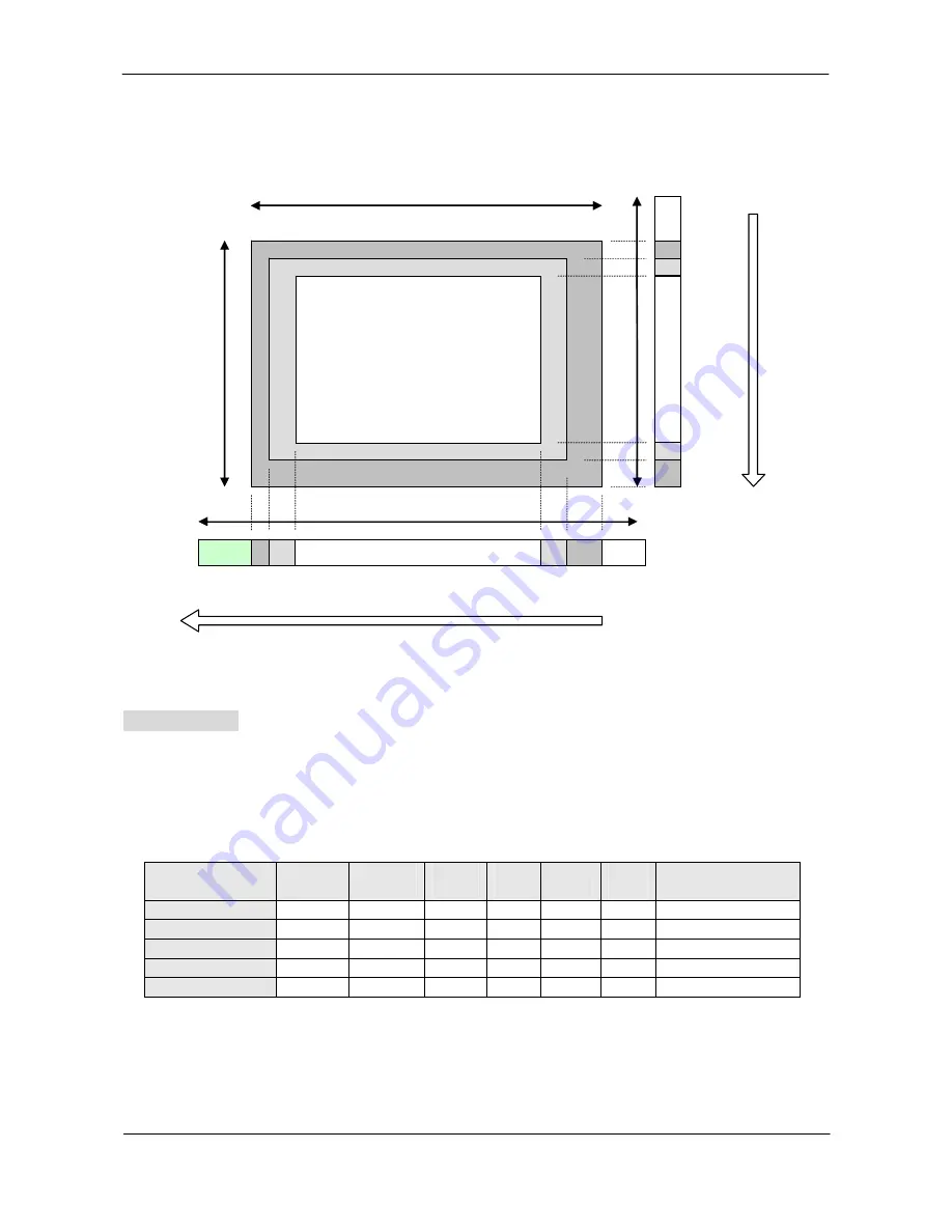
8.4.1. CCD Sensor Layout
Active Pixels
1024(H)x768(V)
Optical Black Lines
Optical Black Lines
Reserved Lines
Reserved Lines
1024
29
3 5
5
4
7
6
2
5
dumm
blank
blank
1420 Clock
Read
Read Out
(Vertical)
4
343
1077
788
768
792
y
Fig. 15. CCD sensor layout
Important Note
: In GigE Vision, only Active Pixel Area is output through the GigE interface.
Dummy, optical black and reserved areas are not output.
Table for scanning
.
The below table shows the start line, the stop line and the number of active lines in the
vertically centered area of the CCD sensor. The front and back lines are the lines used for the
fast dump readout in partial scanning mode.
Scanning
Start
line #
End
line #
Active
lines
Front
lines
Back
lines
Blank
lines
Remarks
Full 1 768
768
12
8
4
Partial 1/2
192
576
384
54
50
4
Partial 1/4
288
480
192
78
74
4
Partial 1/8
336
432
96
90
86
4
V. Binning
1/2
767/768 384 5 4 3
Note:
The following pages show the timing chart for Full, Partial and Vertical binning readout modes.
These timing charts describe internal camera timing and the output through Gigabit Ethernet.
Only the active lines, i.e. 768 lines for full scanning, are output.


