Jacuzzi J-DREAM Owner'S Manual Download Page 32

During the steam bath treatment, the time can always be varied by pressing the (+) and (-) buttons without interrupting
the functions. Also for your convenience, a buzzer will sound when the steam timer reaches zero (00). There is a 10
second delay before the steam bath function is cancelled. During this delay the timer can be reset to allow more steam
bath operation. The steam bath function is controlled with a safety device (indicated by a faucet with a water drop
symbol on the display). This safety device operates in the event that water has been turned off before the steam timer
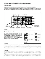
reaches 00.  If the steam water level drops below the minimum level, the red light (13, Figure 1) above the faucet symbol
will come on and an audible signal will sound warning that the water flow from mixer Y has stopped. This occurs
approximately 5 minutes after the flow has ceased. If water is not restored to the steamer unit at this time, the steam
bath function will be cancelled.

The electronic device has a self test program which checks all functions when the power is turned on. All the lights
on the display turn on in a programmed test sequence lasting 8 seconds and testing 14 events. The end of the test
sequence leaves the steam digital time display (Figure 1) reading (--).

In case of power failure while the J-Dream is operating, any function will be completely cancelled.  When power is
restored, the self test will activate and any function can be reset at this time.

The electronic unit is equipped with an internal safety program which automatically cancels any function if a program
has not been completed within 60 minutes.

Before changing from the hydromassage to the steam bath function, or vice versa, the water in the holding tank will
be automatically exchanged, which requires approximately a 60 second waiting period. This feature is incorporated
to decrease deposit buildups in the steam generator.

Use the hand shower while steam is operating

Follow the steps below to operate the hand shower during steam operation without turning off the steam function. This
procedure avoids the drain/fill/heat-up cycle that occurs when the steam control is turned off and back on again at the
control panel.
1. During normal steam operation, the transfer valve is in the middle position as shown in Figure 2  and the mixer valve

is open, or “ON”.

2. Without changing the electronic control panel settings, turn the transfer valve handle to the “handshower”

position. Water will flow from the handshower, and the mixer handle may be used to adjust the water temperature.
The steam mode will continue to function.

3. When you have finished cooling down or rinsing off with the handshower, turn the transfer valve handle back to the

middle position leaving the mixer handle “ON”.
The water flow will stop at the hand shower, and the mixer valve will then continue to provide water to the steam
generator as required.

30

Summary of Contents for J-DREAM

Page 1: ...WHIRLPOOL BATH R J DREAM Shower System OWNER SMANUAL Assembly Installation Operating Instructions...

Page 2: ...infirm and children should not use the J Dream unattended Pregnant women and people with heart conditions should consult their physicians before using the steamer The wet surface of the J Dream can b...

Page 3: ...________ 25 Place Top Cover __________________________________________________________________________ 26 Test for Leaks and Attach Side and Bottom Panels _____________________________________________...

Page 4: ...wer experience Because the J Dream is made by Jacuzzi everything about it from its innovative designandtechnologytoqualitymanufacturing issimply the best Rest on the specially molded seat and relax as...

Page 5: ...JacuzziWhirlpoolBathisnotresponsiblefordamagesresultingfrom excessmoistureorwaterspillage Consult an architect or engineer for aid in designing your interior structure Do not install heat lamps direc...

Page 6: ...oor during exit from the J Dream may cause a walking hazard and or structural damage unless proper waterproof building materials are used in the area surrounding the unit Take into consideration also...

Page 7: ...SCREW M4x10mm SCREW E PAN HEAD SCREW 12 x 1 2 SCREW F HEX BOLT 1 4 20 x 1 5 BOLT G SELF TAPPING M6x50mm BOLT H A NUT J 1 4 20 LOCK NUT LAG SCREW Circled letters A are used in the illustrations of the...

Page 8: ...in the waste line to allow the end of the stubout to be blocked temporarily see page 11 in a position under flush on the floor surface This will allow the shower unit to slide across the floor into p...

Page 9: ...gh flex in the waste line to allow the end of the stubout to be blocked temporarily see page 14 in a position under flush to the floor surface This will allow the shower unit to slide across the floor...

Page 10: ...on of the waste stubout when connected to the shower drain If the stubout is installed before the shower unit leave enough flex in the waste line to allow the end of the stubout to be blocked temporar...

Page 11: ...tion of the waste stubout when connected to the shower drain If the stubout is installed before the shower unit leave enough flex in the waste line to allow the end of the stubout to be blocked tempor...

Page 12: ...s to all four sides of the unit during assembly Allow a minimum of 24 600 mm for access on each side of base Before starting assembly position the base pointing in the same direction as it will be in...

Page 13: ...e locking ring is loose to allow the drain stub to insert easily inside the rubber compression sleeve If necessary lubricate the sleeve with a mild soap solution The drain stub must extend well into t...

Page 14: ...all Pan lip Pan floor Install clip over pan lip locating it over cut out in seat wall and secure with foam tape pre installed on clip Reservoir over flow drain hose will be fed through the clip Clip 1...

Page 15: ...not caulk panel to seat wall as the seat wall is hinged and designed to swing open F Screw 4 C Washer 4 Top View Move Frame Seat Wall When Panel 2 is installed and put in position the seals will be as...

Page 16: ...below Install fasteners Now align the back wall parallel to the pan lip to center the back wall between the seat wall and the end panel Screw 4 B Washer 8 C Nut 4 D Caulk A A Screw 4 B B Caulk Washer...

Page 17: ...1 to Seat Wall Remove 4 bolts from seat wall to attach Panel 1 to seat wall Caulk along surface of seat wall 15 Panel 1 Reinstall bolts 4 and washers 4 removed from seat wall and bracket Seat wall at...

Page 18: ...ation G Hex Bolt 2 This bolt goes through the panel support first and then through the bracket J Nut 2 Reach under the base frame to start the nuts onto the bolts Base Frame N Screw 2 D Nut 4 Spacer B...

Page 19: ...otch does not get screwed against the side panels but faces out as shown in the side view Do not tighten the screws at this time as the angle bracket will have to be aligned with the door frame holes...

Page 20: ...panel Illustration A Attach the bracket to the end panel using this screw Lift the end panel onto the pan and align with Panel 3 Secure the End Panel and Panel 3 as shown in Illustration B The bracket...

Page 21: ...A Remove door frame and angle bracket screws Apply the silicone caulk and reinstall the angle bracket at the marked position Insert screws and tighten Reposition the door frame and install screws thro...

Page 22: ...in door frame with corner of top of frame while aligning with corners of enclosure Illustration A Frame snaps down into door frame and back snaps over back wall Illustration B Install bolts 2 through...

Page 23: ...lines A B and C at the corresponding letters on the mixer Also connect hot and cold water supply hoses Connect control cable Connect ground wire yellow with green stripe to terminal on mixer valve 21...

Page 24: ...io wire bundle from power supply Red lead Black lead CD Radio power supply CD Radio power supply Back of Seat Wall Line A with braided metal sheathing Line B Line B Power Cord Junction Box Attach Line...

Page 25: ...ed ground may be an 8 foot long ground rod 3 meter long earth rod a plate electrode or other acceptable bond Check your local building code for requirements If necessary remove one screw in the plasti...

Page 26: ...protected wall outlet 4 Move the assembled J Dream into final position 5 Connect 2 shower drain see page 12 6 Swing the hinged equipment seat wall open steps A B C below to connect the 3 4 diameter f...

Page 27: ...ector and antenna wire before installing left front panel Illustration B Ground wire is bolted to the seat wall frame 25 Ground Wire Rear view of CD radio B Screw 3 L Front Panel A Remove this screw b...

Page 28: ...J Dream Owner s Manual Place Top Cover Place the clear cover on top of the unit Align notch in cover with the corresponding notch in the top metal frame 26...

Page 29: ...ngle and insert under the bottom of the enclosure frame Rotate backwards till it is up against the brackets with the pre installed Velcro Enclosure Base Frame Front or Side Panel Removable Face Panels...

Page 30: ...ade waterfall the hydromassage and the steam bath The display is composed of four distinct areas with clear symbols to identify the four main functions FIGURE 2 Shower To start the shower carry out th...

Page 31: ...t will automatically be programmed to operate at an average speed of alternation between the groups of water jets and all four groups of jets will be active The intensity of the hydromassage can be ad...

Page 32: ...lled When power is restored the self test will activate and any function can be reset at this time The electronic unit is equipped with an internal safety program which automatically cancels any funct...

Page 33: ...rdwaterarea particlesoflimestonemaybedepositedinthesteamgenerator and reduce its performance Jacuzzi Whirlpool Bath recommends the installation of a water softener unit in order to eliminate or reduce...

Page 34: ...behind and on the seat wall Make sure the power is OFF at the main breaker Remove the top cover Remove the front panel next To do this remove 3 screws securing the panel to the door frame Pull the pa...

Page 35: ...2 bolts 2 places Panel 1 Service Access continued Remove 3 screws along the door frame post Then remove 4 hex head bolts along the seat wall Swing seat wall with Panel 1 toward back wall To reassembl...

Page 36: ...J Walnut Creek CA 94596 510 938 7070 Service Support Call 800 288 4002 Jacuzzi Whirlpool Bath has obtained applicable code standards listings generally available on a national basis for products of th...

Reviews: