background image

5    OPERATION

12

5.5

TRANSPORT WHEELS _____________________________________________________

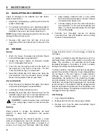
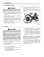
1.

Push and hold the kickstand against the ground then
pull the mower handle back until the mower rests on
the stand 

(L)

.

2.

To remove wheels, press retaining clip 

(M)

 away

from hub and pull wheel off hub.

3.

To install wheels, press retaining clip 

(M)

, place

wheel on hub and turn the wheel backwards until
studs on back of wheel line up with holes in hub 

(N)

.

Push wheel in and release clip.

4.

Always disengage reel switch prior to transporting
the mower more than a few feet.

5.

Push the mower forward off the kickstand, start the
unit and engage the O.P.C. bail.

6.

When using a vehicle to transport the mower, apply
parking brake, turn power off and disconnect power
connector.

Figure 5B

5.6

MOWING_________________________________________________________________

1.

Turn power off. Place mower on kickstand and
remove the transport wheels.

2.

Engage the reel switch. Push the mower forward off
kickstand. Start the unit.

3.

Position mower slightly off green.

a.

Adjust traction speed lever to provide a safe,

comfortable walking speed.

b.

Push handle down to lift mower head above the

grass then engage the O.P.C. bail.

c.

As the mower crosses the edge of the green,

lower the mower head to the ground and
proceed across the green in a straight line.

d.

When the opposite side of the green is reached,

lift the mower head without disengaging the
O.P.C. bail and proceed off the green to turn
around or simply release the O.P.C. bail and turn
around.

Note:

To prevent damage to the reel and bedknife

never

 operate the reels when they are not cutting grass.

Excessive friction and heat will develop between the
bedknife and reel and damage the cutting edge

.

4.

To assure complete even cutting, overlap swaths by
1 to 2 in., (25 or 30 mm) then make one or more
passes around the perimeter of the green to clean
ragged edges and separate the putting green
surface from the apron.


WARNING

Always engage parking brake and disconnect power
connector before installing or removing the transport
wheels.

!

M

N

L


WARNING

To prevent serious injuries, keep hands, feet and
clothing away from cutting unit when the blades are
moving. 

NEVER

 use your hands to clean cutting units. Use a

brush to remove grass clippings from blades. Blades
can be sharp and could cause injuries. 

To clear obstructions from cutting unit, disengage
O.P.C. bail, engage parking brake, turn off power
switch and disconnect power connector then remove
obstruction.

!

Summary of Contents for E-Walk 62290

Page 1: ...Technical Manual GB E Walk 62290 22 11 Blade Reel 4105380 Rev A...

Page 2: ...1 Safety 1 1 Operating Safety 4 1 2 Important Safety Notes 5 2 Specifications 2 1 Product Identification 6 2 2 Electrical System Batteries 6 2 3 Traction and Differential 6 2 4 Mower 7 2 5 Weights 7 2...

Page 3: ...easurement is required to obtain correct adjustment Symbols such as next to the item number indicate that a note exists which contain additional information important in ordering that part Indented It...

Page 4: ...utiously Stay alert for hidden hazards 7 Never direct discharge of material toward bystanders nor allow anyone near the machine while in operation The owner operator can prevent and is responsible for...

Page 5: ...s and maintenance should always be performed by a qualified technician If additional information or service is needed contact your Authorized Jacobsen Dealer who is kept informed of the latest methods...

Page 6: ...d batteries Charger 5 Amp 48 Volt DC dual input voltage 115 230 Volt AC 50 60 Hz Recommended Battery Size USE ONLY 12 VOLT SLA BATTERIES 2 3 TRACTION AND DIFFERENTIAL _________________________________...

Page 7: ...s Lbs kg Weight with batteries catcher Aluminum front roller and kickstand 62290 223 101 2 6 ACCESSORIES SUPPORT LITERATURE _____________________________________ Contact your area Jacobsen Dealer for...

Page 8: ...4 Keep hands feet and clothing away from moving parts 5 Keep bystanders away 1 Leer el manual del operador No permitir que personas no acpacitadas para ello usen la maquina 2 Mantener los escudos en s...

Page 9: ...T F Reel Switch The reel switch is used to start and stop the reel G Hour Meter Records operating hours Used to schedule periodic maintenance H Power Light Indicates unit is energized I Battery Monito...

Page 10: ...ail 2 To test the system the mower must have the transport wheels attached a Place mower on the kickstand b Place reel switch in OFF position 3 Start the unit and place throttle at mid point a Push O...

Page 11: ...rate abnormally Have the equipment repaired before resuming operation 8 Slow down and use extra care on hillsides Use caution when operating near drop offs 9 Look behind and down before backing up to...

Page 12: ...r head above the grass then engage the O P C bail c As the mower crosses the edge of the green lower the mower head to the ground and proceed across the green in a straight line d When the opposite si...

Page 13: ...3 full of grass clippings move the mower off the green 2 Stop on a flat surface disengage O P C bail engage parking brake and disconect power connector 3 Remove and empty the grass clippings from the...

Page 14: ...y the lapping process they must be reground 4 Proper reel to bedknife adjustment is critical A gap of 0 001 to 0 003 0 025 to 0 076 mm must be maintained across the entire length of the reel and bedkn...

Page 15: ...When the reel and bedknife are properly adjusted the reel will spin freely and will cut a piece of newspaper along the full length of the reel when the paper is held at 90 to the bedknife 6 5 BRAKE _...

Page 16: ...d 5 on the opposite end of the reel then tighten nuts M Recheck and readjust the cutting height if necessary Figure 6E 6 7 BELT ADJUSTMENT _______________________________________________________ 1 To...

Page 17: ...set screw and adjust collar Z on OPC bail rod to 4 7 8 in 124 mm from end of rod 3 Test switch and adjust collar up or down as required until switch contacts are open with the OPC disengaged and conta...

Page 18: ...Figure 6J 6 12 FRONT ROLLER WEIGHT___________________________________________________ The weight on the front roller is adjustable between 35 and 45 lb 15 9 20 4 kg Adjust the front roller weight as...

Page 19: ...Nm 75 8 4 100 11 3 107 12 1 143 16 1 9 16 18 ft lb Nm 92 124 122 165 129 174 172 233 1 4 28 in lb Nm 85 9 6 115 13 0 120 13 5 163 18 4 5 8 11 ft lb Nm 113 153 151 204 159 215 211 286 5 16 18 in lb Nm...

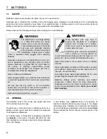
Page 20: ...te spills to the body and eyes with extended flushing with clear water Contact a physician immediately Always wear a safety shield or approved safety goggles when charging batteries Hydrogen is explos...

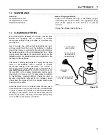
Page 21: ...be left on the batteries which is conductive and will contribute to the discharge of the batteries The correct cleaning technique is to spray the top and sides of the batteries with a solution of sod...

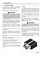
Page 22: ...and check the fuse AC Voltage The charger is equipped with an input voltage selector switch located on the rear of the charger Determine what input voltage is used in your area and set switch accordin...

Page 23: ...brush clean if required Use care to connect the battery wires as shown in Figure 7D and tighten the battery post hardware securely Protect the battery terminals and battery wire terminals with a comm...

Page 24: ...ery tray 1 Park tractor on a solid level area 2 Set parking brake and remove key from switch 3 Disconnect both battery connectors B place mower on kickstand 4 Push and hold battery release latch C dow...

Page 25: ...s 8 2 TIRES ___________________________________________________________________ 1 Keep tires properly inflated to prolong tire life Check pressure only when the tires are cool 2 Use an accurate low pr...

Page 26: ...ghly then repair and paint any damaged or exposed metal 2 Lubricate all fittings and friction points 3 Backlap the reels then back the reel away from the bedknife Apply a light coat of rust preventati...

Page 27: ...tray and check fuse Replace 4 3 Amp fuse blown 4 Check fuse Replace 5 Defective Battery 5 Perform load test replace batteries as needed 6 OPC bail engaged 6 Disengage bail and restart 7 OPC Switch ou...

Page 28: ...nt L4 remove L H transport wheel and mounting bracket E to gain access to fitting Turn the traction drum if pulley F is blocking the fitting then insert grease gun through hole and carefully apply gre...

Page 29: ...NTENANCE LUBRICATION CHARTS 10 29 10 3 LUBRICATION CHART______________________________________________________ F C D B A L 4 L 6 L 6 L7 E G G G G G L 3 L L5 2 L1 Wheel Hub Assembly Pulley Shaft Assemb...

Page 30: ...11 NOTES 30 11 NOTES...

Page 31: ...e Covers 34 3 1 Handle Electronics 35 4 1 Handle Controls 36 5 1 Internal Controls 38 6 1 Battery Case Mounting Tray 40 7 1 Battery Case 42 8 1 Lower Unit 44 9 1 Reel 46 10 1 Belts and Drive Motors 48...

Page 32: ...este equipo desengranar todos los mandos aplicar el freno de estacionamiento y disconnectar el conector de poder 4 Manterer las manos los pies y la ropa alejados de las piezas en movimiento 5 Manterer...

Page 33: ...On Off 3 4104281 1 Decal Ground Speed 4 4122712 1 Decal E Pac 5 3005144 1 Decal Danger 6 3002753 1 Decal Parking Brake 7 3002756 1 Decal Bale Handle Control 8 4104283 1 Decal Warning 9 4104282 1 Deca...

Page 34: ...Decals 2 4103280 1 Cover Bottom 3 3006436 1 Switch Reel Reference SW3 See 14 1 4 2811676 2 Contactor 48V Reference K1 and K2 See 14 1 5 366768 2 Throttle Knob 6 404014 7 Screw 1 4 20 x 12 Round Head 7...

Page 35: ...asher 6 32 Internal Tooth 4 444304 6 Nut 6 32 Hex 5 REF 1 Relay Run See 13 1 6 3004520 1 Fuse Holder 7 1000348 1 Power Switch Reference SW1 See 14 1 8 447222 1 Lockwasher 9 16 Internal Tooth 9 358968...

Page 36: ...1 2 3 4 5 8 10 11 14 15 18 19 20 21 22 24 25 15 7 9 27 15 25 36 16 41 40 26 28 30 39 38 37 34 35 31 32 33 29 Inverted View 13 5 42 43 44 A A 18 18 6 12 23 17 45 E WALK 4 1 Handle Controls Serial No A...

Page 37: ...20 443110 2 Nut 3 8 16 Hex 21 1001292 2 Bracket Assembly 22 443102 2 Nut 1 4 20 Hex 23 4108460 1 Plate Spring 24 400268 1 Screw 3 8 16 x 1 3 4 Hex Head 25 446142 3 Lockwasher 3 8 Heavy 26 366743 1 Thr...

Page 38: ...38 20 21 22 23 View from underneath handle stem 12 13 14 15 16 17 18 19 14 14 18 1 2 3 4 5 6 7 8 9 10 11 3 7 11 26 24 27 28 25 29 30 31 32 33 6 30 33 6 E WALK 5 1 Internal Controls Serial No All...

Page 39: ...Hex Head 14 453009 3 Flat Washer 5 16 15 446136 1 Lockwasher 5 16 Heavy 16 443106 1 Nut 5 16 18 Hex 17 452008 1 Flat Washer 3 8 18 2811680 1 Potentiometer Reference R1 See 14 1 19 4108740 1 Gear Speed...

Page 40: ...40 1 2 6 7 7 9 10 12 11 13 14 15 16 17 17 10 9 16 3 13 14 13 14 5 3 8 4 4 8 9 9 9 9 9 10 10 5 11 4 16 13 14 B B 4 3 E WALK 6 1 Battery Case Mounting Tray Serial No All...

Page 41: ...2 Spring Extension 6 2811206 1 Clip 7 4104360 3 Spacer 8 4104361 2 Spacer 9 443102 8 Nut 1 4 20 Hex 10 446130 4 Lockwasher 1 4 Heavy 11 400108 2 Screw 1 4 20 x 3 4 Hex Head 12 443106 3 Nut 5 16 18 Hex...

Page 42: ...42 1 2 3 4 Terminal Hardware Battery and Battery Monitor Connections 2 2 3 5 6 6 7 8 9 9 10 12 22 11 23 13 14 14 4 1 See Above 15 18 19 20 21 16 17 E WALK 7 1 Battery Case Serial No All...

Page 43: ...Cable Jumper 10 403741 8 Screw 8 32 x 5 8 Hex Head 11 444306 8 Nut 5 16 18 Hex 12 446112 8 Lockwasher 8 Heavy 13 4101600 2 Strap Battery Case 14 2811669 1 Battery Monitor Includes Hard ware Reference...

Page 44: ...9 17 24 10 11 27 8 8 24 8 10 28 19 43 21 8 3 15 10 16 7 12 12 14 13 6 16 18 9 8 8 23 25 1 2 26 22 20 20 19 4 17 5 10 8 10 A A 29 30 44 31 32 34 35 36 37 33 38 9 39 40 41 36 39 40 36 42 42 E WALK 8 1 L...

Page 45: ...x 1 1 4 Hex Head 19 443810 4 Nut 3 8 16 Hex Jam 20 400268 2 Screw 3 8 16 x 1 3 4 Hex Head 21 3008674 1 Grass Shield 22 365501 2 Bolt Bedknife Mounting Shoe 23 454017 2 Spring Washer 24 366796 2 Kickst...

Page 46: ...46 28 25 29 30 7 8 9 6 5 5 4 15 31 13 15 19 2 1 3 24 27 23 22 16 17 18 20 21 26 10 11 12 30 15 14 32 33 34 E WALK 9 1 Reel Serial No All...

Page 47: ...5 16 18 x 1 2 Socket Head 15 446136 6 Lockwasher 5 16 Heavy 16 367164 1 Spacer Reel Shaft 17 453011 1 Flat Washer 3 8 18 400294 1 Screw 3 8 24 x 3 4 Hex Head 19 4105360 3 Screw 5 16 18 x 2 1 4 Socket...

Page 48: ...48 A A 1 2 3 4 5 6 7 8 9 10 12 11 13 14 15 16 18 21 22 23 24 25 26 27 31 32 33 28 30 29 12 14 15 17 19 20 32 28 15 E WALK 10 1 Belts and Drive Motors Serial No All...

Page 49: ...oupler Assembly 14 367554 2 Bearing Needle 15 446130 9 Lockwasher 1 4 Heavy 16 443102 3 Nut 1 4 20 Hex 17 400190 1 Screw 5 16 18 x 1 1 4 Hex Head 18 452006 3 Flat Washer 5 16 19 446134 1 Lockwasher 5...

Page 50: ...50 9 10 3 29 20 16 21 30 31 8 6 4 11 7 5 5 22 21 35 35 36 34 1 2 24 32 17 27 28 20 20 16 26 25 15 14 15 13 19 18 23 12 33 6 E WALK 11 1 Parking Brake and Transport Wheels Serial No All...

Page 51: ...se Seal 16 366717 2 Clutch Sleeve 17 445801 2 Nut 5 8 18 Hex Jam Lock 18 434049 6 Screw 5 16 18 x 2 Socket Head 19 366718 2 Latching Collar 20 366697 4 Bushing 21 446136 2 Lockwasher 5 16 Heavy 22 400...

Page 52: ...52 24 22 21 23 26 27 29 19 17 31 25 25 28 30 2 5 4 6 7 8 1 12 12 13 13 14 10 16 14 3 1 15 15 11 9 18 28 20 19 24 32 E WALK 12 1 Differential and Rollers Illustration Description 2 Serial No All...

Page 53: ...Thrust Washer 13 202947 2 Pinion Gear 14 415563 2 Set Screw 7 16 20 x 3 8 15 463007 2 Key 7 Wooodruff 16 308028 1 Pinion Shaft 17 220318 1 Bearing Housing 18 220319 1 Bearing Housing 19 366693 2 Bear...

Page 54: ...ntactor Reel Motor Traction Motor Key Switch To Relay To 6A Fuse To Soft Start Timer Reel Switch To Hour Meter 2 3 7 12 8 4 5 6 5 3 4 5 6 6 9 10 2 4 7 1 4 11 To Diode Traction Speed Control Run Relay...

Page 55: ...e K4 See 14 1 2811690 1 Relay Low Battery Reference K5 See 14 1 2 3008474 1 Clamp 3 345666 2 Clamp 4 452006 1 Flat Washer 5 16 5 446134 3 Lockwasher 5 16 6 443106 3 Nut 5 16 18 Hex 7 453023 3 Flat Was...

Page 56: ...1 B 2 B 3 LoBat U1 1 B 2 B BATTERY CONTROLS BK BK OG BK OG BK OG VT OG BK SW1 B I Y X A S F2 1 2 RD OG RD OG BU OG BU OG RD OG RD OG RD OG RD K4 COM CL1 NO CL2 NC SW2 NO1 NO2 NC1 NC2 B1 B2 F1 B3 B4 J...

Page 57: ...BU BU BK BK BK BK WH LIGHT OPT RD OG RD OG RD K2 NO CL NO CL GY YE GY YE SW3 2 3 RD RD J2 2 J2 1 RD RD GY GY BN GY BN L1 A B C D K L J H G F E 1 6 2 5 4 3 M M S S S SHLD BK M1 R1 OG RD OG RD C A B K1...

Page 58: ...676 Reel Contactor K4 See 13 1 4103540 Run Relay Included with Harness K5 See 13 1 2811690 Low Battery Relay Included with Harness L1 Not Shown 4108221 Headlight with Switch Included in Light Kit L2 S...

Page 59: ...98 Six 12 Ounce Orange Aerosol 2500789 Twelve 1 Quart Can Orange 546409 Two 1 Gallon Can Orange Lapping Compound 5002488 One 10 Pound Pail of 80 Grit 5002490 One 25 Pound Pail of 80 Grit 5002489 One 1...

Page 60: ...47 338766 51 345666 55 352737 45 359864 49 360111 51 361451 51 53 363047 47 364164 45 364441 45 364900 47 365501 45 47 365753 51 366648 47 366650 47 366653 45 366693 53 366695 53 366696 53 366697 51...

Page 61: ...61 INDEX...
Page 62: ...p com Equipment from Jacobsen is built to exacting standards ensured by ISO 9001 and ISO 14001 registration at all of our manufacturing locations A worldwide dealer network and factory trained technic...

Reviews: