


TABLE DIMENSIONS
CORNER INSTALLATION
TABLE DIMENSIONS
CONNECTION TO DISHMACHINE
TABLE DIMENSIONS STRAIGHT
THROUGH INSTALLATION
C
OPENING
D
E
A
B
A
C
OPENING
D
C
G
F (ROLL)
A
B
D
C
OPENING
D
LETTER
DIM (IN) DIM (CM)
A
4” (MIN) 10.2 CM (MIN)
B
2 1/2”
6.4 CM
C
20 1/2”
52.1 CM
D
25 1/4”
64.1 CM
E
2 1/4”
10.2 CM
F
1 1/2”
3.8 CM
G
3/4”
1.9 CM
9
INSTALLATION INSTRUCTIONS
INSTALLATION & OPERATION
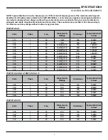
Jackson WWS Inc. provides technical support for all of the dishmachines detailed in this manual and recommends that
service personnel have this manual on hand when calling technical support staff. Technical support is available from 8:00
a.m. to 5:00 p.m. (EST), Monday through Friday. Technical support is not available on holidays. Contact technical support
toll free at 1-888-800-5672. Please remember that technical support is available for service personnel only.
VISUAL INSPECTION:
Before installing unit check container and machine for damage. A damaged container may be an
indication of damage to the machine. If there is any type of damage to both container and unit, do not throw away the
container. The dishmachine has been inspected at the factory prior to shipping and is expected to arrive in new, undamaged
condition. However, rough handling by carriers or others may result in damage to the unit while it is in transit. If such a
situation occurs, do not return the unit to the manufacturer. Instead, contact the carrier and ask them to send a representative
to the site to inspect the damage, and request that an inspection report be completed.
Contact the carrier within 48 hours of receiving the machine (to report possible freight damage) and the dealer from whom
the unit was purchased.
UNPACKING THE DISHMACHINE:
The machine should be unboxed and removed from the pallet prior to installing. Open
the front door and remove all of the materials from the inside. Once unpacked, verify there are no missing parts. If a part
is missing, contact manufacturer immediately.
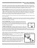
LEVEL THE DISHMACHINE:
The dishmachine is designed to operate while level. This is
important to prevent any damage to the machine during operation and to ensure the best
results possible. The unit comes equipped with adjustable bullet feet which can be turned
using a pair of pliers. Verify the unit is level from front to back and side to side before making
any electrical or plumbing connections.
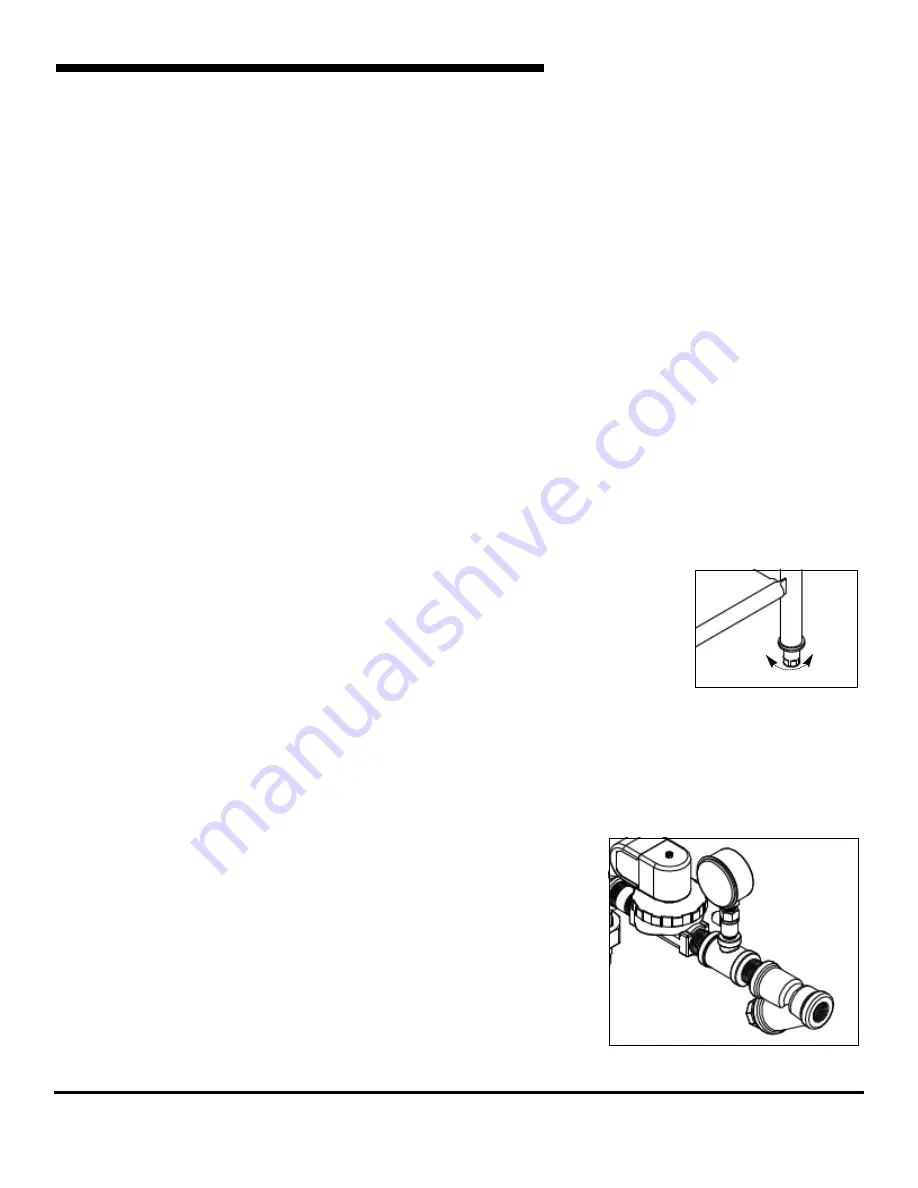
PLUMBING THE DISHMACHINE:
All plumbing connections must be made to adhere to local,
state, territorial and national codes. The installing plumber is responsible for ensuring the in-
coming water lines are flushed of debris prior to connecting to the machine. Note that chips and
materials from cutting processes can become lodged in the solenoid valves and prevent them from opening or closing. Any
valves that are found to be fouled or defective because of foreign matter left in the water line, and any subsequent water
damage, are not the responsibility of the manufacturer.
A water hardness test must be performed to determine if the HTS-11 (scale prevention & corrosion control) needs to be
installed. A hardness test kit can be found on the warning tag that is attached to
the incoming plumbing connection on
the back of the machine. If water hardness is higher than 5 GPG, the HTS-11 will
need to be installed. Please contact manufacturer to purchase the HTS-11.
CONNECTING THE DRAIN LINE:
The dishmachine's drain is a gravity discharge
drain. All piping from the 1 1/2” FNPT connection on the wash tank must be pitched
(1/4” per foot) to the floor or sink drain. All piping from the machine to the drain must
be a minimum 1 1/2” I.P.S. and shall not be reduced. There must also be an air
gap between the machine drain line and the floor sink or drain. If a grease trap is
required by code, it should have a flow capacity of 5 gallons per minute.
Incoming Plumbing Y-strainer Connection
Frame with Adjustable Foot
Raise
Lower
Summary of Contents for TempStar Series
Page 2: ......
Page 28: ...PARTS 22 TOP MOUNTED CONTROL BOX ASSEMBLY 30 28 29 25 22 21 26 33 34 36 1...
Page 36: ...PARTS HOOD ASSEMBLY 30 1 5 4 2 3 6 7 10 8 9...
Page 60: ...PARTS 460 VOLT MACHINE TRANSFORMER MOUNTING BOX 54...
Page 61: ...PARTS PARTS 55 EXHAUST FAN CONTROL OPTION...
Page 66: ...ELECTRICAL SCHEMATICS SOLID STATE TEMPSTAR HH TOP MOUNT CONTROLS 208 230V 60HZ 1 3 PHASE 60...
Page 67: ...ELECTRICAL SCHEMATICS 61 TEMPSTAR HH UNIVERSAL TIMER 208 230V 60HZ 1 3 PHASE...
Page 68: ...ELECTRICAL SCHEMATICS 62 SOLID STATE TEMPSTAR HH TOP MOUNT W CYCLE SWITCHES 460V 60HZ 3 PHASE...
Page 69: ...ELECTRICAL SCHEMATICS TEMPSTAR HH UNIVERSAL TIMER 460V 60HZ 3 PHASE 63...
Page 70: ...ELECTRICAL SCHEMATICS TEMPSTAR HH S UNIVERSAL TIMER 208 230V 60HZ 1 3 PHASE 64...
Page 71: ...ELECTRICAL SCHEMATICS TEMPSTAR HH 208 230V 60HZ 1 3 PHASE 65...
Page 72: ...ELECTRICAL SCHEMATICS TEMPSTAR HH 460V 60HZ 3 PHASE 66...
Page 73: ...ELECTRICAL SCHEMATICS TEMPSTAR HH S 208 230V 60HZ 1 3 PHASE 67...
Page 74: ...ELECTRICAL SCHEMATICS TEMPSTAR HH NB 208V 230V 50 60HZ 1 PHASE 68...
Page 75: ...ELECTRICAL SCHEMATICS TEMPSTAR HH NB LT 208V 230V 50 60HZ 1 PHASE 69...
Page 76: ...70 ELECTRICAL SCHEMATICS OPTIONS SDI OPTION...
Page 77: ...ELECTRICAL SCHEMATICS OPTIONS EXHAUST FAN HOOKUP DRAIN QUENCH OPTIONS 71...
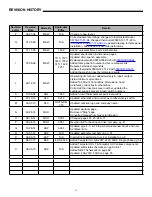
Page 78: ...Tempstar HH Series Installation Operation Technical Manual 07610 002 23 32 Issued 09 14 07...