background image

13

07610-002-23-32-AD

OPERATING INSTRUCTIONS

OPERATION

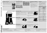
Before operating the unit, verify the following:

1.  The tank is clean and free of debris.
2.  The wash arms, rinse arms, sump strainer, and scrap screen are all installed 

correctly.

3. 

The standpipe is installed.

To energize the unit, turn on the power at the service breaker. The voltage should 

have  been  previously  verified  as  being  correct.  If  not,  the  voltage  will  have  to  be 
verified.

Ensure that the mode switch is in the "AUTO" position, and place the power switch 

into  the  "ON"  position.  The  machine  will  fill  automatically  and  shut-off  when  the 

appropriate level is reached (just below the scrap screen). The wash tub must be 

completely filled before operating the wash pump to prevent damage to components. 
Once the wash tub is filled, the unit is ready for operation.

Proper ware preparation will help ensure good results and fewer re-washes. If not 

prepared properly, ware might not come out clean and the efficiency of the machine 

will be reduced. Putting unscraped dishes into the machine affects its performance, 
so scraps should always be removed from ware before being loaded into a rack. 
Pre-rinsing and pre-soaking are good ideas, especially for silverware and casserole 
dishes. 

Place cups and glasses upside-down in racks so they don't hold water during the 
cycle. The machine sanitizes as well as cleans. To do this, ware must be properly 
prepared before being placed in the machine.

Refer to the “Preparation” section and follow the instructions there. Afterward, ensure 

that chemicals are supplied to the machine. If not, contact your chemical supplier.

PREPARATION

POWER UP

WARE 

PREPARATION

FILLING THE 

WASH TUB

DAILY MACHINE 

PREPARATION 

Standpipe

Wash & Rinse Arms, Scrap Screen

Sump Strainer

Summary of Contents for TEMPSTAR HH S

Page 1: ...TEMPSTAR HH E INSTALLATION OPERATION AND SERVICE MANUAL TempStar HH E Manual 07610 002 23 32 AD TEMPSTAR SERIES DOOR TYPE DISHMACHINES ...

Page 2: ...lled by Jackson at the factory and are shipped with the Dishmachine carry only a 1 one year parts warranty Labor to repair or replace these components is not included in the warranty or covered by Jackson Booster heaters not manufactured by Jackson are not covered by this warranty but are warranted by their respective manufacturers This warranty is void if any defect or failure is a direct result ...

Page 3: ...M DEFECTS IN MATERIALS AND WORKMANSHIP AND IS REPORTED TO JACKSON WITHIN 30 THIRTY DAYS FROM THE DATE OF INSTALLATION 9 DAMAGE CAUSED BY LABOR DISPUTE 10 DAMAGES RESULTING FROM IMPROPER CONNECTION TO UTILITY SERVICE 11 DAMAGES RESULTING FROM WATER CONDITIONS INADEQUATE OR EXCESSIVE WATER PRESSURE ACCIDENTS ALTERATIONS IMPROPER USE ABUSE HANDLING OVERLOADS TAMPERING IMPROPER INSTALLATION OR FAILURE...

Page 4: ...setpoint instructions L 1 10 13 RLC 8252 Updated schematic and control box to reflect rotary switch M 3 7 13 RLC QOF NDB 219 Updated Jackson logo and company name N 3 24 14 MHH Updated warranty page Removed Stop page Converted manual from Quark to InDesign O 4 16 14 MHH 8291 Changed pgs 22 25 28 and 31 P 6 4 14 MHH 8287 New P N for bearing on rinse arm assembly pg 41 Q 10 28 14 KAP 8298 Updated pg...

Page 5: ...ematics Updated to new manual format Audited and corrected all P Ns in the manual AC 9 9 17 JH 8541 8543 Added the TempStar HH E and associated parts and assemblies Moved door switch from the Tub Assembly page to the Hood Assembly page Added door switch bracket assembly to the Hood Assembly page Updated schematics on pgs 76 and 77 AD 10 16 18 JH 8392 8480 8533 8536 8558 8567 8576 8599 Replaced the...

Page 6: ...nitizing no rinse booster TempStar HH S Door type dishmachine steam heated high temp hot water sanitizing The manufacturer provides technical support for all of the machines detailed in this manual We strongly recommend that you refer to this manual before making a call to our technical support staff Please have this manual open when you call so that our staff can refer you if necessary to the pro...

Page 7: ...npacking 8 HH E VER Assembly 8 Leveling 8 Plumbing 8 Water Supply Connection 8 Steam Line Connection 9 Pressure Regulator 9 Shock Absorber 9 Connecting the Drain Line 9 Exhaust Fan Timer 9 Chemical Connections 10 Plumbing Check 10 Electrical Power Connections 11 Motor Rotation 11 Voltage Check 12 Surrounding Area 12 Temperature Setpoints 12 False Panel Corner Install 12 Facility Hot Water Heater 1...

Page 8: ...ection 14 Shutdown Cleaning 14 VER Coil Cleaning 16 Detergent Control 17 Deliming 18 MAINTENANCE Preventative Maintenance 19 TROUBLESHOOTING Common Problems 20 PARTS Control Box 22 Hood 26 Door Arm 28 Tub 30 Steam Tub 33 Frame 35 Rinse Tank 36 Steam Coil 38 Motors 39 Heaters 41 Plumbing HH E 42 Plumbing HH E VER 44 Inlet Plumbing HH S 46 Outlet Plumbing HH S 47 Plumbing Options 48 TABLE OF CONTENT...

Page 9: ...m Door Interlock Override 55 460 V Machine Transformer Mounting Box 56 Kits 57 SCHEMATICS HH E HH E VER 208 230 V New Rinse Tank 58 HH E HH E VER 460 V New Rinse Tank 59 HH E HH E VER 208 230 V Old Rinse Tank 60 HH E HH E VER 460 V Old Rinse Tank 61 NB 208 230 V 62 NB 460 V 63 HH S 208 230 V 64 SDI Options 65 TABLE OF CONTENTS ...

Page 10: ...link ANSI American National Standards Institute Btu Hr British Thermal Units per Hour CFM Cubic Feet per Minute GHT Garden Hose Thread GPH Gallons per Hour GPM Gallons per Minute GPG Grains per Gallon HP Horsepower Hz Hertz ID Inside Diameter kW Kilowatts MCA Minimum Circuit Ampacity MOP Maximum Overcurrent Protection NFPA National Fire Protection Association NPT National Pipe Thread OD Outside Di...

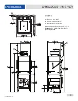
Page 11: ...E 863 4 2203 mm WITH DOOR OPEN A 73 1854 mm 17 432 mm C B 28 5 8 727 mm 25 635 mm 1 4 15 387 mm LEGEND A Drain 1 1 2 NPT B Water Inlet 3 4 NPT C Electrical Connection increased 2 using the machine s adjustable feet 73 1856mm 4 102 mm MINIMUM 4 124 mm 7 8 5 8 A 4 102 mm MINIMUM 20 508 mm D D 5 1 2 140 mm D Optional Steam Connection 3 4 NPT DIMENSIONS SPECIFICATIONS ...

Page 12: ...mm 73 1856mm 34 861mm 93 2362mm B 88 2235mm C 10 mm 51 4 134mm LEGEND A Drain 1 1 2 NPT B Water Inlet 3 4 NPT C Electrical Connection increased 2 using the machine s adjustable feet 4 2 85 8 72 7 mm CLEARANCE 2 6 6 8 8 7 32 5 8 A B MINIMUM DIMENSIONS HH E VER SPECIFICATIONS ...

Page 13: ...8 1 4 210 mm Distance from wall to rear rack rail Distance from wall to right rack rail Control Panel 1 1 4 32 mm 1 3 8 35 mm 20 1 2 521 mm OPENING 30 762 mm 8 1 4 210 mm 20 1 2 521 mm OPENING 4 102 mm MIN ALIGN WITH TABLE DISTANCE CAN VARY Distance from wall to rear rack rail Control Panel 20 1 2 521 mm OPENING For corner install instructions CORNER INSTALLATION STRAIGHT THROUGH INSTALLATION ...

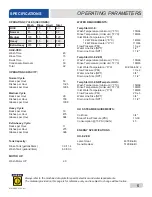
Page 14: ...PSI 10 2 Water Line Size NPT 1 2 Drain Line Size NPT 1 1 2 TempStar HH E VER Wash Temperature minimum F C 155 68 Rinse Temperature minimum F C 180 83 Inlet Water Temperature F C 40 90 4 4 32 2 Flow Pressure PSI 10 2 Water Line Size NPT 3 4 Drain Line Size NPT 1 1 2 TempStar HH E NB Tempstar HH S Wash Temperature minimum F C 150 66 Rinse Temperature minimum F C 180 83 Inlet Water Temperature F C 18...

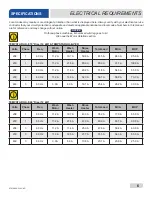
Page 15: ...MOP 208 1 60 Hz 11 2 A 19 7 A 43 3 A 74 2 A 77 0 A 85 0 A 230 1 60 Hz 11 2 A 21 8 A 47 9 A 80 9 A 83 7 A 90 0 A 208 3 60 Hz 11 2 A 11 4 A 25 0 A 47 6 A 50 4 A 60 0 A 230 3 60 Hz 11 2 A 12 6 A 27 7 A 51 5 A 54 3 A 65 0 A 460 3 60 Hz 3 0 A 6 3 A 13 8 A 23 1 A 23 9 A 25 0 A ELECTRICAL REQUIREMENTS SPECIFICATIONS On three phase machines imbalanced wild leg goes to L3 Also see the Motor Rotation sectio...

Page 16: ...R HH E NB Volts Phase Freq Wash Motor Wash Heater Rinse Heater Total Load MCA MOP 208 1 60 Hz 11 2 A 19 7 A N A 30 9 A 33 7 A 40 0 A 230 1 60 Hz 11 2 A 21 8 A N A 33 0 A 35 8 A 45 0 A 208 3 60 Hz 11 2 A 11 4 A N A 22 6 A 25 4 A 35 0 A 230 3 60 Hz 11 2 A 12 6 A N A 23 8 A 26 6 A 35 0 A 460 3 60 Hz 3 0 A 6 3 A N A 9 3 A 10 1 A 15 0 A TEMPSTAR HH S Volts Phase Freq Wash Motor Wash Heater Rinse Heater...

Page 17: ...unit comes with four adjustable bullet feet which can be turned using a pair of channel locks or by hand if the unit can be raised safely Ensure that the unit is level from side to side and front to back before making any connections Plumbing connections must comply with all applicable local state and national plumbing codes The plumber is responsible for ensuring that the incoming water line is t...

Page 18: ...pressure with flow pressure Static pressure is the line pressure in a no flow condition all valves and services are closed Flow pressure is the pressure in the fill line when the fill valve is opened during the cycle The manufacturer also recommends the installation of a shock absorber in the incoming water line and offers these devices as options This prevents line hammer hydraulic shock induced ...

Page 19: ...tor and replacing it with the appropriate dispensing equipment See Plumbing HH E VER page for a depiction of the VER rinse injector Rinse aid Using deionized water or other aggressive fluids will result in corrosion and failure of components and will void the warranty WARNING Some of the chemicals used in dishwashing may cause chemical burns if they come in contact with skin Wear protective gear w...

Page 20: ...Improperly connecting external devices can cause damage to the machine and or electrical infrastructure Click here for a wiring guide On 3 Phase machines only correct pump motor rotation must be verified before the machine is operated Failure to do so can result in damage to the machine and components 1 Follow the Filling the Wash Tub section 2 Locate the wash pump motor and identify the arrow dec...

Page 21: ...ected with these higher temperatures in mind Any damage to surrounding area caused by heat moisture to materials that are not recommended for higher temperatures will not be covered under warranty or by the manufacturer The temperature setpoints on this unit have been set at the factory They should only be adjusted by an authorized service agent The manufacturer offers an optional False Panel Kit ...

Page 22: ...ub is filled the unit is ready for operation Proper ware preparation will help ensure good results and fewer re washes If not prepared properly ware might not come out clean and the efficiency of the machine will be reduced Putting unscraped dishes into the machine affects its performance so scraps should always be removed from ware before being loaded into a rack Pre rinsing and pre soaking are g...

Page 23: ...automatically Once the cycle is complete open the door again watching for the dripping hot water and remove the rack of clean ware Replace with a rack of soiled ware and close the door Repeat this process Based on use the scrap screen might become clogged with soil and debris as the workday progresses Operators should regularly inspect the scrap screen to ensure it has not become clogged If clogge...

Page 24: ... Remove the sump strainer and scrap screen 5 Use a hand scraper to scrape foodsoil into a trash basket 6 Rinse with pre rinse hose and replace 7 Remove all wash and rinse arms 8 Remove the end caps from the arms 9 Clean nozzles with a brush SHUTDOWN CLEANING ...

Page 25: ...ut interior of the machine 14 Replace wash and rinse arms 15 Ensure sump strainer and scrap screen are clean and securely in place 16 Use stainless steel polish to clean and protect outside of machine The coil on the VER machine must be inspected periodically If the coil is greasy dirty or there is scale build up click here for cleaning instructions SHUTDOWN CLEANING OPERATING INSTRUCTIONS OPERATI...

Page 26: ... Discuss this option with a qualified water treatment specialist 4 Machine operators should be properly trained on how much detergent is to be used per cycle Meet with a water treatment specialist and detergent vendor to discuss a complete training program for operators 5 These machines require that chemicals be provided for proper operation and sanitization and require the installation of third p...

Page 27: ...ical supplier 6 Flip the mode switch to AUTO to shut the unit off 7 Open the door and step away for five minutes 8 Inspect the inside of the machine If the machine is not delimed run again 9 When clean drain and re fill the machine 10 Run two cycles in AUTO to remove residual deliming solution 11 Drain and re fill the machine 12 Flush rinse arms with water and replace CAUTION This equipment is not...

Page 28: ... all strainers are clean and securely in place before operating the machine When cleaning out strainers do NOT beat them on waste cans Wipe out strainers with a rag and rinse with water if necessary Use a toothpick to dislodge any stubborn debris 3 Ensure all wash and rinse arms are secure in the machine before operating 4 Ensure the standpipe is in position before operating 5 Remove as much soil ...

Page 29: ...mer is faulty 2 Wash motor faulty damaged 3 Wash motor contactor faulty 1 Verify the timer is receiving power If so replace the timer assembly 2 Verify the wash motor is getting power If so replace the motor 3 Check for continuity if contacts are open replace the contactor Machine runs continuously in the wash cycle 1 Machine is in Delime mode 2 Timer motor is faulty 3 Cam timer jammed by obstruct...

Page 30: ...eter Door will not close completely 1 Improper spring tension 2 Obstruction in door channel 3 Door panels are not square with frame 1 Adjust spring tension as required by loosening not removing spring bolt nuts and adjusting the tension Tighten nuts back when done 2 Remove the obstruction 3 Adjust the frame to accommodate the door panels Water leaks at the wash pump 1 Wash pump seal defective 2 Pe...

Page 31: ...E AID DISPENSER CONNECTION DETERGENT DISPENSER CONNECTION LIVE WHEN MACHINE POWER SWITCH IS ON LIVE WHEN RINSE VALVE IS OPEN LIVE WHEN WASH PUMP MOTOR IS ON L1 OUT L2 OUT FUSE 3 AMP SLOW ACTING L1 OUT L2 OUT FUSE 3 AMP SLOW ACTING L1 OUT L2 OUT FUSE 3 AMP SLOW ACTING MAXIMUM LOAD 1 AMP 240 120 VAC EXHAUST FAN CONTROL WARNING DISCONNECT POWER TO MACHINE BEFORE SERVICING INPUT L1 EXTERNAL OUTPUT TO ...

Page 32: ...23 07610 002 23 32 AD 13 9 10 42 40 41 12 15 11 14 27 8 39 37 6 2 6 7 6 5 32 16 31 6 6 6 4 23 24 6 20 18 17 CONTROL BOX PARTS 17 18 6 20 8 2 7 6 6 5 32 16 6 6 23 24 4 4 6 6 31 37 39 43 ...

Page 33: ... 150 F Min 09905 002 97 61 15 1 Decal Rinse 180 F Min 09905 002 97 62 16 1 Ground Lug 05940 200 76 00 17 1 Bracket Liquid Level Control Board 05700 002 13 22 18 1 Liquid Level Control Board 06680 200 08 21 19 6 Tricnut 6 32 05340 118 04 00 20 3 Screw 6 32 x 5 8 05305 011 39 85 21 3 Plug 1 2 05975 011 47 81 22 2 Grommet 7 8 Split 05975 200 40 00 23 1 Bushing Snap 05975 210 05 00 24 1 Clamp Hose 25 ...

Page 34: ... 32 x 1 Not Shown 05305 002 19 42 40 1 Switch Rotary Selector 05930 003 97 61 41 1 Switch Operation 05930 301 53 00 42 1 Switch Power 05930 011 49 55 43 1 Exhaust Fan Timer One Shot 05945 004 34 92 43a 1 Din Rail One Shot Timer Not Shown 05935 004 47 77 43b 1 Screw Phillips Pan Washer Not Shown 05305 004 47 78 44 1 Overload TK ONY 460 V Unit Only Not Shown 05945 002 65 02 45 1 Motor Contactor SC 0...

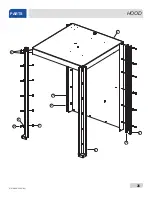
Page 35: ...07610 002 23 32 AD 26 1 5 4 2 3 6 7 10 8 9 HOOD PARTS ...

Page 36: ... 05700 031 76 33 7 34 Locknut 1 4 20 Hex with Nylon Insert 05310 374 01 00 8 26 Washer 1 4 20 05311 174 01 00 9 6 Screw 1 4 20 x 5 8 Hex 05305 274 24 00 10 20 Bolt 1 4 20 x 1 2 05305 274 02 00 HOOD PARTS ITEM QTY DESCRIPTION PART NUMBER 1 1 Complete Assembly Bracket Magnet Mounting Bracket Magnet Mounting 05700 004 48 16 05700 004 47 83 2 1 Bumper Door 05700 004 14 25 3 1 Magnet N50 05930 003 31 6...

Page 37: ...07610 002 23 32 AD 28 DOOR ARM PARTS 9a 9b 9b 9c 9d 9e 3 See previous page Before ordering door or arm parts see the note on the next page NOTICE ...

Page 38: ...ing 05700 002 00 91 11 4 Plate Spring Multiplier 05700 002 00 88 12 4 Spring Cantilever Door 05340 111 35 22 13 2 Bolt Cantilever Hanger Eye 3 8 16 05306 956 05 00 14 2 Washer Impeller 05311 176 02 00 15 4 Locknut 1 4 20 Low profile with Nylon Insert 05310 374 02 00 16 4 Bolt 1 4 20 x 1 2 Hex 05305 274 02 00 17 4 Nut 3 8 16 Hex 05310 276 01 00 18 1 Right Door Complete Assembly 05700 004 51 86 19 1...

Page 39: ...07610 002 23 32 AD 30 TUB PARTS 12 11 10 13 15 11 14 34 37 36 33 26 35 31 30 29 27 28 24 25 22 23 21 4 20 19 18 16 16 17 3 1 2 3 5 6 7 9 38 32 8 19b 19c 19a ...

Page 40: ...Not Shown 05700 002 91 55 13b 1 Ball Stop Lift Not Shown 05700 002 91 54 14 1 Overflow Support Bracket 05700 001 27 55 14a 1 Shim Overflow Support Not Shown 05700 002 96 48 15 1 O ring 05330 400 05 00 16 2 Clamp Hose 1 5 16 to 2 1 4 04730 719 01 37 17 1 Discharge Hose 05700 011 88 24 18 1 Nipple 05700 021 34 84 19 1 Pump Support Bracket Assembly 05700 002 00 46 19a 1 Nut 1 4 20 Hex Nut 05310 011 6...

Page 41: ... 00 30 1 Cover Wash Heater 05700 031 47 57 31 1 Decal Warning Disconnect Power 09905 004 08 16 32 1 Harness 5 Connector 05700 004 23 78 33 1 Thermostat Mounting Bracket 05700 004 22 17 34 1 Wash Heater Gasket 05330 011 47 79 35 1 Probe Thermistor 4 06685 004 17 26 36 1 Thermostat High Limit 05930 004 33 12 37 1 Fitting 1 4 Imperial Brass 05310 924 02 05 38 1 Harness 4 Connector 05700 004 23 79 ...

Page 42: ...3 21 4 20 19 18 16 16 17 3 1 2 3 5 6 7 9 30 24 26 32 33 31 35 34 8 STEAM TUB PARTS ITEM QTY DESCRIPTION PART NUMBER 1 1 Tub Weldment HH Steam 05700 002 63 13 2 1 Track Assembly 05700 002 01 00 3 2 Bulk Head Plug 04730 609 05 00 4 1 Wash Motor See Motors page 36 ...

Page 43: ... 4 04730 719 01 37 17 1 Discharge Hose 05700 011 88 24 18 1 Nipple 05700 021 34 84 19 1 Pump Support Bracket Assembly See Item 19 on Tub pages 20 1 Clamp Hose 5 5 8 to 6 04730 011 34 90 21 1 Connector 1 2 05975 111 01 00 22 4 Nut 3 8 16 Hex 05310 276 01 00 23 4 Lockwasher 3 8 05311 276 01 00 24 1 Fitting 1 4 Imperial Brass 05310 924 02 05 25 1 Probe High Water 06680 200 02 68 26 1 Thermostat High ...

Page 44: ...QTY DESCRIPTION PART NUMBER 1 1 Frame Frame 460 V 05700 002 03 49 05700 002 62 41 2 4 Adjustable Foot 1 1 2 Adjustable Foot 3 Adjustable Foot Flanged 05340 108 02 06 05340 002 14 55 05340 002 01 15 3 1 Front Dress Panel 05700 002 01 42 1 2 3 ...

Page 45: ...it Thermostat 05700 004 36 84 12 2 Nut 1 4 20 05310 004 23 96 13 4 Washer 1 4 20 05311 174 01 00 14 4 Locknut 1 4 20 Hex with Nylon Insert 05310 374 01 00 15 1 Clamp Wire 1 8 P clip 05975 601 10 15 16 1 Cover Door New Rinse Tank 05700 004 52 21 17 1 Washer Flat 05311 173 02 00 18 1 Locknut Hex 8 32 05310 272 02 00 19 1 Plug 1 4 Brass Not Shown 04730 209 01 00 RINSE TANK PARTS Complete Assemblies 2...

Page 46: ...cknut 10 24 with Nylon Insert 05310 373 01 00 9 4 Locknut 1 4 20 with Nylon Insert 05310 374 01 00 10 4 Washer 1 4 Flat 05311 174 01 00 11 1 Cover Rinse Tank 05700 002 16 51 12 1 Decal Warning Disconnect Power 09905 004 08 16 Complete Assemblies 208 230 V 14 kW 70 Rise 06401 004 55 19 208 230 V 12 kW 40 Rise 06401 004 55 20 460 V 14 kW 70 Rise 06401 004 55 21 460 V 12 kW 40 Rise 06401 004 55 22 RI...

Page 47: ...700 021 41 38 2 1 Stand C Steam Coil Support 05700 002 08 52 3 1 Stand D Steam Coil Support 05700 002 08 53 4 1 Gasket Steam Coil 05700 001 17 86 5 2 Washer Steam Coil 05700 001 17 87 6 2 Adapter Steam Coil Nut 05310 011 17 85 7 1 Stand A Steam Coil Support 05700 002 08 50 8 1 Stand B Steam Coil Support 05700 002 08 51 STEAM COIL PARTS ...

Page 48: ... is important to refer to the wiring schematic found on the motor to ensure the motor is wired correctly Different manufacturers of motors might not use the same wire color codes and your new motor might not connect using the same wires Always refer to the wiring diagrams on the motor you are installing If the motor you are installing has had the schematic removed contact the manufacturer immediat...

Page 49: ...eal 460 V 05330 002 87 16 4 4 Motor Bolt 05700 002 82 55 5 1 Motor Adapter 05330 002 82 53 6 1 Motor Only 06105 002 82 60 7 1 Seal Plate 208 230 V 05700 002 82 52 1 Seal Plate 460 V 05700 002 06 22 8 1 Case O ring 208 230 V 05330 002 34 23 1 Case O ring 460 V 05330 002 87 02 9 8 Case Screws 05305 002 81 88 10 1 Shim Kit 208 230 V Not Shown 05700 002 82 58 1 Shaft Adapter 460 V Not Shown 05700 011 ...

Page 50: ...4540 121 63 39 TempStar HH E Volts Hz Phase Wash Heater Rinse Heater 14 kW 208 50 1 04540 121 47 39 04540 121 63 38 208 50 3 04540 121 47 39 04540 121 63 38 208 60 1 04540 121 47 39 04540 121 63 38 208 60 3 04540 121 47 39 04540 121 63 38 230 50 1 04540 121 47 39 04540 121 63 38 230 50 3 04540 121 47 39 04540 121 63 38 230 60 1 04540 121 47 39 04540 121 63 38 230 60 3 04540 121 47 39 04540 121 63 ...

Page 51: ...07610 002 23 32 AD 42 PLUMBING HH E PARTS Top View Back View Before ordering plumbing parts see the note on the next page NOTICE ...

Page 52: ...Gasket Rinse Manifold 05330 003 75 91 When servicing plumbing components take care not to damage the threads of each individual item Damaged threads can cause leaks and loss of pressure which could adversely affect the performance of the machine It is strongly recommended that teflon thread tape used in conservative amounts be applied to threads when joining components together It is not advised t...

Page 53: ...07610 002 23 32 AD 44 PLUMBING HH E VER PARTS APPROX 45 BACK OF MACHINE 13 14 Before ordering plumbing parts see the note on the next page NOTICE ...

Page 54: ... 07 37 14 1 Gasket Rinse Injector 05330 111 42 81 When servicing plumbing components take care not to damage the threads of each individual item Damaged threads can cause leaks and loss of pressure which could adversely affect the performance of the machine It is strongly recommended that teflon thread tape used in conservative amounts be applied to threads when joining components together It is n...

Page 55: ...ducing 3 4 to 1 2 04730 911 02 34 Union 3 4 NPT Black Iron 2 per assembly 04730 912 01 01 3 4 NPT Black Iron Pipe 05700 002 20 83 Gate Valve 3 4 NPT 04820 100 19 00 Bracket Steam Plumbing Support 05700 002 20 83 Y Strainer 3 4 NPT Black Iron 04730 217 01 32 Solenoid Valve Steam Plumbing 220V 04820 002 01 32 To order this complete assembly use part number 05700 002 01 60 2 1 3 4 5 6 7 10 8 9 INLET ...

Page 56: ... Black Iron Pipe 05700 002 20 83 Gate Valve 3 4 NPT 04820 100 19 00 Bracket Steam Plumbing Support 05700 002 20 83 Y Strainer 3 4 NPT Black Iron 04730 217 01 32 Solenoid Valve Steam Plumbing 220V 04820 002 01 32 To order this complete assembly use part nu 05700 002 01 55 To order this complete assembly use part number 05700 002 01 60 OUTLET PLUMBING HH S PARTS 1 2 3 4 5 When servicing plumbing com...

Page 57: ...1 27 00 Nipple 1 2 Close Brass 04730 207 15 00 SHOCK ABSORBER WATER ARRESTOR OPTION Pressure Gauge 0 100 PSI 06685 111 88 34 Ball Valve 1 4 Bronze 04810 011 72 67 Water Pressure Regulator 1 2 04820 100 04 07 Water Pressure Regulator 3 4 VER 06685 011 58 22 Tee Brass 1 2 x 1 2 x 1 4 04730 411 25 01 Adapter 1 2 04730 011 59 53 WATER TREATMENT OPTION Replacement Cartridge inspect at least every 6 mon...

Page 58: ...hragm Retainer Diaphragm 06401 003 07 42 Screen Retainer Mesh Screen Valve Body Complete 240 Volt Solenoid Valve Assembly 04810 100 03 18 Coil Housing only 06401 003 07 44 Complete Vacuum Breaker Assembly 04820 002 53 77 Components of Repair Kit 06401 003 06 24 Cap Screw Data Plate Cap O Ring Plunger Body Cap Retainer Spring Plunger 06401 003 07 40 O ring Diaphragm 06401 003 07 42 ...

Page 59: ...11 12 15 15 2 3 4 5 7 17 8 6 18 18 18 18 18 2 3 19 5 21 9 18 1 7 21 17 10 1 5 9 WASH RINSE ASSEMBLIES PARTS 16 16 16 16 17 11 13 14 1 10 5 9 7 19 15 2 3 4 5 1 16 9 16 6 15 8 19 7 2 3 12 5 17 18 RINSE ARMS MANIFOLD WASH ARMS MANIFOLD 20 ...

Page 60: ...m 05700 004 54 71 13 2 Complete Rinse Arm Assembly 05700 004 47 74 2 Rinse Arm 05700 004 47 56 14 4 Rinse Arm End cap 04730 111 60 41 15 1 Lower Wash Manifold Weldment 05700 002 21 70 16 5 Locknut 1 4 20 Hex with Nylon Insert 05310 374 01 00 17 1 Rinse Manifold Weldment 05700 002 01 19 18 2 Bolt Hex 3 8 16 x 1 1 4 05305 276 10 00 19 1 Wash Arm Double Assembly 05700 003 94 00 1 Wash Arm Double Asse...

Page 61: ...07610 002 23 32 AD 52 VER SYSTEM PARTS 18 24 23 12 11 16 17 14 21 22 20 19 27 28 29 ...

Page 62: ... 003 06 13 12 1 Elbow 1 2 90 degree Street Brass 04730 206 08 00 13 1 Bracket Vacuum Breaker 05700 004 18 91 14 1 Shroud Heat Exchanger 05700 004 18 92 15 6 Locknut 10 24 Hex with Nylon Insert 05310 373 01 00 16 6 Washer Flat 05311 173 02 00 17 1 Inlet Cold Water 05700 004 19 01 18 2 Fan 85 236 VAC Corrosion resistant 05999 004 19 46 19 2 Screw 1 4 20 x 5 8 Hex Head 05305 274 24 00 20 1 Edge Prote...

Page 63: ...h 04820 004 24 11 5 1 Spring Compression 05935 004 24 10 6 1 Base Door Interlock Box 05700 004 24 25 7 8 Screw 3 8 Pan Head 05305 171 02 00 8 8 Washer Flat 10 05311 173 02 00 9 2 Locknut 1 4 20 05310 374 01 00 10 2 Washer 1 4 20 05311 174 01 00 11 1 Fitting Black 05975 011 59 50 12 2 Connector 2 Conductor 05935 004 03 49 13 1 SJ Cord 55 05700 004 24 31 2 4 6 5 1 9 10 7 8 3 13 11 12 VER SYSTEM DOOR...

Page 64: ...ock option These instructions should only be used if the door interlock fails to unlatch and the doors won t open 1 Turn machine off by flipping the power switch to OFF 2 If this doesn t disengage the interlock rod push the rod back by hand 3 The door should now open 4 Contact a qualified service agency to have the interlock serviced ...

Page 65: ...ANSFORMER MOUNTING BOX PARTS 460 V Transformer 05950 111 65 93 2 A Circuit Breaker 05925 111 64 18 Transformer Mounting Box 05700 002 10 01 Transformer Mounting Box Top Not Shown 05700 000 78 53 Transformer Mounting Bracket 05700 031 62 82 ...

Page 66: ...it 06401 004 03 23 Door Magnet Cover Kit 06401 004 07 73 Drain Water Tempering Kit 06401 004 07 86 Exhaust Fan Contactor Kit 05700 004 35 35 False Panel Kit 05700 002 52 89 Phase Conversion Kit 06401 004 00 22 TempStar Go Box Kit 06401 003 62 04 The Go Box is a kit of the most needed parts to successfully complete a repair in the first call 90 or more of the time ...

Page 67: ...07610 002 23 32 AD 58 SCHEMATICS HH E VER 208 230 V NEW RINSE TANK ...

Page 68: ...59 07610 002 23 32 AD SCHEMATICS HH E VER 460 V NEW RINSE TANK ...

Page 69: ...07610 002 23 32 AD 60 SCHEMATICS HH E VER 208 230 V OLD RINSE TANK ...

Page 70: ...61 07610 002 23 32 AD SCHEMATICS HH E VER 460 V OLD RINSE TANK ...

Page 71: ...07610 002 23 32 AD 62 SCHEMATICS NB 208 230 V ...

Page 72: ...63 07610 002 23 32 AD SCHEMATICS NB 460 V ...

Page 73: ...07610 002 23 32 AD 64 SCHEMATICS HH S 208 230 V ...

Page 74: ...65 07610 002 23 32 AD SCHEMATICS SDI OPTIONS ...

Page 75: ......

Page 76: ...Jackson WWS Inc 6209 N US Hwy 25E Gray KY 40734 USA 1 888 800 5672 www jacksonwws com TempStar HH E Manual 07610 002 23 32 AD ...

Reviews: