background image


1

 / 

14


ZB-A4F electric control box manual 


·


Safety Precautions 

·


Before using this product, please read the User's Guide and the manual of the machine attached with it. 

·


This product must be installed or operated by professionally trained personnel. 

·


Please keep away from the arc welding equipment to avoid the electromagnetic wave from interfering with the 
controller. 

·


Please do not use it at room temperature above 45°or below 0°


·


Please do not use it in places with humidity below 30% or above 95% or where there is dew and acid mist.   

·


When installing the control box and other parts, turn off the power and unplug the power plug. 

·


To prevent interference or electric leakage accidents, make a good grounding work. The grounding wire of the 
power cord must be firmly connected to the earth. 

·


All parts for maintenance must be supplied or approved by the Company before they can be used. 

·


The power must be turned off and the plug unplugged before any maintenance action is performed.There is a 
high-voltage danger in the control box. You must shut down the power for 5 minutes before opening the control 
box. 

1    Product Installation 

1.1 product specification 

Voltage 

AC 220±20% V 

Supply frequency


50Hz/60Hz 

maximum output power


550W 

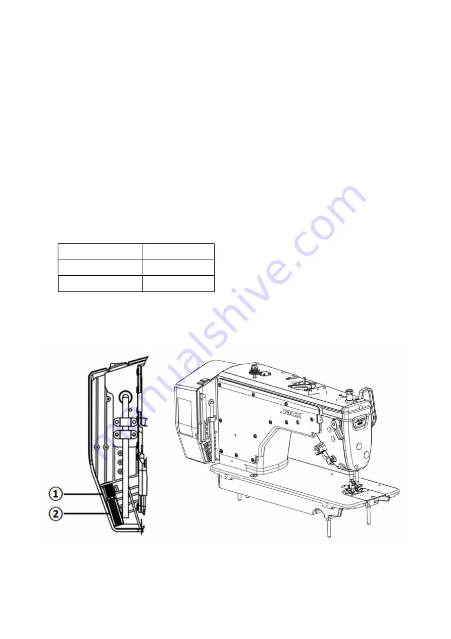
1.2 The connection of interface plug 

Insert the connecting plugs of the foot pedal and the head of the machine into the corresponding socket at the back of the 

controller. Each socket names are shown in figure 1-2-2.Please check whether the plug is inserted. 


Summary of Contents for ZB-A4F

Page 1: ...rference or electric leakage accidents make a good grounding work The grounding wire of the power cord must be firmly connected to the earth All parts for maintenance must be supplied or approved by the Company before they can be used The power must be turned off and the plug unplugged before any maintenance action is performed There is a high voltage danger in the control box You must shut down t...

Page 2: ...ating Socket of Electromagnet LED Lamp and machine head 1 2 2 controller connection plug definition If it cannot be inserted normally please check the plug and socket match or not the direction of the insertion or the direction of the needle is correct or not ...

Page 3: ...troductions 2 1 display introduction According to the working status of the system the LCD of the operation panel will display the current sewing status including the needle position indicate The appearance of the operation panel is shown as below 2 1 appearance of operation panel 2 2 function declaration of each key Key Name Indicate 1 Stitch length adjustment key Stitch length adjustment key pre...

Page 4: ...responding key to set A B C D 2 Press the key for long time icon is lit means now is Several Segment Tacking mode choose corresponding key to set all steps and all stitches of each step 9 Lock stitch key Needle position section key Press short time to this key the lock stitch function will switch to front lock rear lock front and back lock close Press long time to enter needle position function 10...

Page 5: ...ne to enter technician parameter mode The methods is same as parameter mode 3 3 Speed adjustment Press and to adjust the speed For up to adjust fast for down to adjust slow each adjustment value is 50 3 4 Factory setting Press the for a long time back to the factory setting 3 5 Enter monitoring system Press to enter this mode press up and down key to adjust this parameter press P then can log out ...

Page 6: ...ngth to 5mm long press stitch length plus or press stitch length minus to enter the sewing parameter modification interface In the parameter modification interface short press the or key to switch the modified parameter position press the or key to modify the stitch length compensation parameter size P171Stitching needle length compensation ratio P172Reverse stitching needle length compensation ra...

Page 7: ...1 Max speed of manual reverse sewing r min 2800 200 3200 P22 Value of backstitch during half stitch 8 0 9999 P23 curve mode of pedal 0 0 3 0 straight 1 Slope 2 curve square extraction of a root 3 S curve P24 Pedal position of trimming 550 0 4095 P25 Stitch compensation of back tacking 1 0 0 10 P26 Stitch compensation of back tacking 2 0 0 10 P27 Sensor press foot lifter mode selection 0 0 1 0 clos...

Page 8: ...f down needle position 176 0 359 P34 Multi segment sewing motion mode selection 0 0 1 0 one key start function off 1 one key start function off P35 Thread clamp switch 1 0 1 P36 Threads testing ending angle 25 1 360 P37 Thread clamp magnet closing time 4 2 10 P38 Trimmer switch 1 0 1 0 off 1 on P39 Press foot lifter in halfway 0 0 1 0 off 1 on P40 Switch of auto press foot lifter after trimming 0 ...

Page 9: ...ow speed 800 0 4095 P74 Max value of pedal analog 4000 0 4095 P75 Setting of pedal back to middle position 1650 0 4095 P78 Thread clamp ending angle 130 10 359 P79 Thread clamp end angle 320 0 359 P80 Trimming starting angle 0 0 359 P81 Trimming strength angle 100 0 359 P82 Trimming ending angle 180 0 359 P83 Pedal presser foot confirmation time ms 150 1 500 P84 The confirmation time of Safety swi...

Page 10: ...ength key mode change EN 0 0 1 0 Off 1 On P107 Safety needle break selection switch 1 0 1 0 Off 1 On P108 Safety needle break starting mechanical angle 20 0 359 P109 Safety needle break finished mechanical angle 90 0 359 P110 Fixed stitches trimmer in sewing and then bartack selection switch 0 0 1 0 Off 1 On P116 Single seaming function switch 0 0 1 0 Off 1 On P123 Duty cycle of full opening phase...

Page 11: ... foot height adjust 0 999 999 P177 Press down speed 300 50 1000 P179 Press up speed 400 50 1000 P181 Press height limit 13 0 13 P182 Stepmotor press up time 10 0 9999 P183 Stepmotor stitch act angle length change 150 0 359 P184 Stepmotor keep current 28 1 50 P185 Stitch length keep time 0 0 10 P186 Stepmotor target location adjust 6 0 30 P187 Stepmotor current limit 70 60 80 P193 1 2 stitch length...

Page 12: ...rovider or call 4008876858 Err 05 Overvoltage during operation Disconnect the controller power and check whether the input power voltage is higher than 264V If so please restart the controller after the voltage returns to normal If the voltage returns to normal it still does not work properly after the controller starts up Please contact your local service provider or call 4008876858 Err 06 Electr...

Page 13: ...roller still does not work properly please contact your local service provider or call 4008876858 Err 15 Arm shaft motor overspeed protection Err 16 Arm shaft motor reverse Err 17 Pandel date read write failure Turn off the system power and then turn on the power again after 30 seconds If the controller still does not work properly please contact your local service provider or call 4008876858 Err ...

Page 14: ...tions If so replace it in time 3 If the system still does not work properly after troubleshooting and restart Please contact your local service provider or call 4008876858 Err 29 Reverse stitch stepping motor encoder AB signal abnormal 1 Check whether the backstitch step motor swing seat and teeth are stuck After the normal state is restored restart the system 2 Check whether the backstitch step e...

Reviews: