Jabiru Aircraft
Pty Ltd
Installation Manual
Jabiru 3300 Aircraft Engine
REVISION
0
1
2
3
4
5
6
7
Dated : 1
st
Dec 2016
Page: 45 of 56
12.2
Flow Visualisation
In designing the cooling system the designer must have a basic understanding of how air flows and behaves
inside the cowl. The pictures below are intended to explain it in simple terms.
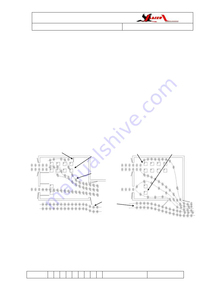
Figure 49 shows two schoolrooms, drawn as if seen from above. Each room represents an engine and oil
cooler inside a cowling.
i.
There are two doors in the inlet side of the room and one on the outlet side.
ii.
Several desks are placed in the room, representing the engine cylinders and the oil cooler.
iii.
Students walk through from left to right, representing the air flow through the cowls.
iv.
On each desk is a pile of homework papers, representing heat generated by the engine.
Air always takes the path of least resistance. It tries to escape quickly to the playground without taking the
homework.
The desks and doorways form restrictions. If the desks are too close, not enough students can pass
through. If the desks are too far apart some students will not pick up their homework. If the inlet doorways
are too large then there will be a traffic jam trying to get out of the outlet door.
Gaps can leave room for students to pass without picking up homework.
Given a group of desks as shown, students can follow many paths through them
– from front to rear, from
top to bottom or any combination.
Slowing down the students as they pass through the desks means they will pick up their homework, but if
they are slowed down anywhere else it only reduces the amount of students that can get through the room.
If the exit becomes jammed with people, installing bigger inlet doors will not increase the number of students
passing through the room. Exits should be as clear and free of obstructions as possible to let people out.
Students will often have a preferred desk to take their homework from, meaning that some cylinder heads
will have more heat removed than others
– temperatures will wary between different heads.
Figure 49. Flow Visualisation
- Partitions are used to force the students to walk
through the desks.
- Each student picks up the homework.
- Outlet door is 90° to the flow of students in the
corridor; there is no restriction & jostling at the exit
- No partitions are used, so students walk around
the desks instead of through them.
-
Most students don’t come close enough to a desk
to pick up the homework
- Outlet door is parallel to the flow of students in the
corridor, causing restriction & jostling at the exit
Desk
Students carrying
homework
Students in the
corridor
“Oil cooler” desks
“Cylinder head” desks
Partition


