background image


11

6. INSTALLATION 


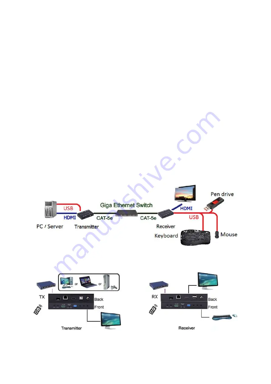
6.1 Device Connection 

 
1.    Check the power supply is unplugged. 
2.    Set up the group of the transmitter with the correspondent receiver for 
signal extension and display. 
3.    Connect the Transmitter to video source with HDMI cable, and connect 
Receiver to a monitor or display with HDMI cable. 
4.    Connect the USB cables from Transmitter to PC, and connect the USB 
additional devices such as USB mouse, USB keyboard and USB pen drive to 
Receiver. 
5.  Connect Transmitter and Receiver to the Ethernet switch with network 
cable. 
6.  Power on the Transmitter, Receiver and all the connected devices. 
7.    Power on and activate all the connected devices. 
8.  Connect the IR extension cable with Transmitter and the IR receiver 
cable with Receiver for remote control. 


Configuration


Summary of Contents for JTECH-VW-4KPR

Page 1: ...1 4K HDMI USB KVM Extender over IP Fiber With POE Operation Instructions...

Page 2: ...tion 17 7 1 System 17 7 1 1 Version Information 17 7 1 2 Update Firmware 18 7 1 3 Utilities 19 7 1 4 Statistics 20 7 2 Video Wall 21 7 2 1 Basic Setup 21 7 2 2 Advanced Setup 25 7 3 Network 29 7 3 1 I...

Page 3: ...xtension and RS232 control 4 bits switch for 16 stream channel selection Support Dolby True HD DTS HD Master Audio Support two way Wide Band IR extension 38khz 56khz Transmit over single Cat5e 6 cable...

Page 4: ...1x RJ45 output 1x Fiber output RS232 Phoenix RS232 port IR 1x IR TX port 1x IR RX port Support 38K 56KHz Connectors on Receiver Input 1xRJ45 input 1x Fiber input Output 1x HDMI Female port 2x USB A ty...

Page 5: ...en LED Link LED when the connection has established over Cat5e 6 cable or Fiber cable the Green LED will illuminate B Yellow LED When the yellow LED is blinking it indicates the conne ction has been e...

Page 6: ...LED when the connection has established over Cat5e 6 cable or Fiber cable the Green LED will illuminate B Yellow LED When the yellow LED is blinking it indicates the conne ction has been established o...

Page 7: ...on Link Link off Unlink Video Mode Graphic Mode Long Press 3 sec Snoop on off Anti Dither 1 2 off N A Anti Dither 1 2 off Short Press when Ethernet Link is Off BYPASS BYPASS BYPASS BYPASS Long Press w...

Page 8: ...e a half tone effect However this presents great difficulty for Video Compression to maintain low bandwidth even if the source display seems static Currently we only see Dithering Output with ATI grap...

Page 9: ...back Video Mode Graphic Mode Link on Link Link off Unlink Video Mode Graphic Mode Long Press 3 sec Snoop on off Anti Dither 1 2 off USB Link on off Anti Dither 1 2 off Short Press when Ethernet Link i...

Page 10: ...ID feature is used for Multicast Mode to select which monitor TV EDID is used for system wide EDID usage During multicast setup there maybe monitor TV that has lower resolution For example 1 monitor T...

Page 11: ...y with HDMI cable 4 Connect the USB cables from Transmitter to PC and connect the USB additional devices such as USB mouse USB keyboard and USB pen drive to Receiver 5 Connect Transmitter and Receiver...

Page 12: ...12 Application Pattern Unicast Multicast a Video Distribution...

Page 13: ...13 b Matrix Distribution c Billboard Kiosk PC to HDMI and USB Interactive Monitor...

Page 14: ...er IP Extender can configure via LAN in the same subnet 1 Assign a LAN IP address to the computer in the same subnet The IP address default of the Transmitter and Receiver is B class Networking 169 25...

Page 15: ...hing we need know the IP address of each unit There is two way to get the IP address 1 Via Node List Open the Node List in the Tool file Press twice the Node_list bat to enter the dialog box Then we c...

Page 16: ...ate the 4K HDMI USB Over IP Extender 3 After activation the device information including the Transmitter and Receiver IP address will be shown in the lower right corner Remember the Transmitter and Re...

Page 17: ...enter the Extender Web UI If link success administrator will see the Web UI as shown in Figure 4 Figure4 Web User Interface 7 WEB USER INTERFACE CONFIGURATION 7 1 System The relevant information of th...

Page 18: ...ansmitter Firmware Update please select webfw bin to update Receiver Firmware Update please select webfwc bin to update It takes time to update the firmware During the process of update the Web user i...

Page 19: ...lities There are some functions Factory Default Click on to return to the factory default when necessary Reboot Click on to reboot the extender system Console API Command Input Linux command for advan...

Page 20: ...20 7 1 4 Statistics Indicating the extender linking and working status...

Page 21: ...tside width and height OW outside width OH outside height VW viewable width VH viewable height Please NOTE 1 The viewable width must be less than the outside width and the viewable height must be less...

Page 22: ...22 Wall Size and Position Layout Select number of vertical and or horizontal monitors row position and column position Vertical monitor number 1 8 horizontal monitor number 1 16...

Page 23: ...23 Preferences Select the video fit in the screen or stretch out and the rotate angle...

Page 24: ...er in the same Group IP 2 This Local The IP you input into address bar of web browser 3 Hosts or Clients select which Transmitter or Receiver you want to configure Show OSD Check this box to output ea...

Page 25: ...25 7 2 2 Advance Setup...

Page 26: ...complete the Basic Setup as follows Step1 In Basic Setup select Vertical and Horizontal Monitor Count For example Vertical Monitor Count 3 Horizontal Monitor Count 5 Sept2 In Advanced Setup choose th...

Page 27: ...o Fit In or Stretch Out mode in the screen Setup the rotation angle of the video output Set up the number of vertical and horizontal monitor based on the video wall layout Vertical number 1 8 and hori...

Page 28: ...or Setup the video position shift and video enlarge Horizontal Shift Setup the video horizontal shift Left or Right Vertical Shift Setup the video vertical shift Up or Down Horizontal Scale Up Setup t...

Page 29: ...API Command Input Linux command to do advanced setup 7 3 Network Update the network setup of the extender system 7 3 1 IP Setup Auto IP use automatically Extender assign IP system for example 169 254...

Page 30: ...IP sharer to assign IP Static use the static IP to assign manually 7 3 2 Casting Mode Select the broadcast mode of the extender application Multicast point to multiple points or multiple point to mul...

Page 31: ...31 7 4 Functions Setup the video output and USB extension mode for Transmitter Setup the video output and USB extension mode for Receiver...

Page 32: ...vers Scaler Output Mode Select the required scalar output mode or select customize and input 8 Hex values for more video output resolution and refresh rate selections 1 80000004 HD 720p60 2 81000061 W...

Page 33: ...4 2 USB over IP Setup the USB extension mode Enable USB over IP Check to enable USB extension mode over IP Operation Mode Including auto select mode active on line and active per request modes for opt...

Page 34: ...34 7 4 3 Serial over IP set up the serial extension mode Select Type 2 as operation mode Set up the baud rate for Type 2 Serial Over IP Broadcast Mode Setting...

Page 35: ...Multicast To enable the USB interactive devices controlled by turns please check Auto select USB operation mode per casting mode 8 2 Unicast 8 3 Matrix Install multiple transmitters and setting ID of...

Page 36: ...p 2 Set up the horizontal monitor count to 5 Step 3 Set up the row position of the monitor to 0 Step 4 Set up the column of the monitor to 0 Step 5 Apply the setting to the extender system Administrat...

Page 37: ...reen in video wall matrix layout Take below diagram for example the monitor we select to control here is the monitor in the upper left corner Example for the video wall control Here s the diagram of t...

Page 38: ...eration was input Reset Adjust the horizontal position of the video output Left Right Shift the selected monitor to adjust is shown with green outline Adjust the vertical position of the video output...

Page 39: ...9 Horizontal Scale Up To scale up the video output horizontally as the monitor shown with green outline Vertical Scale Up To scale up the video output vertically as the monitor shown with green outlin...

Page 40: ...be reached LIMITED WARRANTY LIMITS AND EXCLUSIONS This Limited Warranty ONLY COVERS failures due to defects in materials or workmanship and DOES NOT COVER normal wear and tear or cosmetic damage The...

Reviews: