40
9.4 Control of air volume
The air volume is determined by the speed of the impeller and the underpres-
sure in the mounting curb, see the graph §4.1.
The speed can be determined by:
• measuring with the aid of a stroboscope;
• reading the speed with the VU Control Unit in the ‘Status’ menu under
‘Speed’.
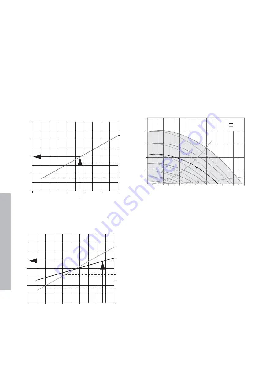
• measuring the voltage on the ‘Esoll’ and ‘GND U3’ clamps and plotting
these measured values in the applicable graph on page 14. These graphs
only apply if the MX has been set at minimum speed 15%* and maximum
speed 100% [this is the standard factory setting]. If these settings are
different, the applicable graph must be adjusted accordingly. This method
is not applicable for ZMV.
*The minimum capacity of the MX 30/20 has been factory set at 25%.
Example: MX 20/10
Speed rpm [min-1]
Capacity [%]
Measured voltage 5.5V
Speed is 1000rpm
Example: MX 20/10
Speed rpm [min-1]
Capacity [%]
Speed rpm 9 [min-1] Capacity [%]
Minimum capacity setting 40%
Maximum capacity setting 80%
Measured voltage 8.7 V
Speed is 1200 rpm
The underpressure can be determined by:
• measuring the underpressure in the mounting curb;
• reading the underpressure with the VU Control Unit in the ‘Status’ menu
under ‘Sensor’. However: this is only possible for the ZMV and when the
measuring point of the pressure transmitter is located in the mounting curb.
The air volume can now be determined.
• Now plot the speed line found in the graph §4.1.
☞
Take notice of that you use the line with or without silencer [GD]?
• Now draw a line from the underpressure found to the right.
• Draw a line vertically from the intersecting point found and determine the
air volume.
Example
A. = maximum power consumption and B = maximum sound pressure level
Example
Speed 1200 rpm
No silencer
Underpressure 120 Pa
Air volume is 1900 m3/h
Conclusions
More air than the design value means that the resistance in the system is
lower than the design value.
Possible causes are:
• lower duct resistance than assumed;
• valves or grilles have not be fitted or adjusted [open too far];
• leakage in the duct system. Compare the air volume with the total
measured air volume through the valves.
Less air than the design value means that the resistance in the system is
higher than the design value.
Possible causes are:
• higher duct resistance than assumed;
• valves or grille not adjusted [too far closed];
• blockage in the duct system. Compare the air volume with the total
measured air volume through the valves.
500
400
300
200
100
0
0
400
800
1200 1600
1600
1400
1200
1000
800
600
400
A
B
2000 2400 2800
3200
3600
m
3
/h
∆
Pst - Pa (N/m
2
)
= MX
= MX + GD
2000
1500
1000
500
0
0
2
4
6
8
10
E
soll
- GND (V)
0
25
50
75
100
80
40
2000
1500
1000
500
0
0
2
4
6
8
10
E
soll
- GND (V)
0
25
50
75
100
English


